A multi-directional restraint device for ballasted track bed

A restraining device and track technology, applied in the direction of tracks, roads, ballast layers, etc., can solve the problems of insufficient structural constraints of the ballast bed, insufficient longitudinal and lateral resistance, etc., to reduce the number of maintenance, improve the average force, increase the area and effect of depth

Active Publication Date: 2016-07-06
KUNMING UNIV OF SCI & TECH
View PDF5 Cites 0 Cited by
  • Summary
  • Abstract
  • Description
  • Claims
  • Application Information

AI Technical Summary

Problems solved by technology

[0005] The invention provides a multi-directional restraint device for a ballasted track bed, which is used to solve the problems of insufficient structural restraint and insufficient longitudinal and transverse resistance of the existing railway track bed

Method used


Image

  • A multi-directional restraint device for ballasted track bed
  • A multi-directional restraint device for ballasted track bed
  • A multi-directional restraint device for ballasted track bed

Examples


Embodiment 1

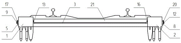
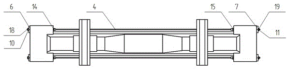
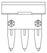
[0040] Example 1: Such as Figure 1-9 As shown, a multi-directional restraint device for a ballasted track bed includes a reinforced concrete block on the left side of the line 1, a reinforced concrete block on the right side of the line 2, a screw rod I3, a screw rod II4, an internal thread fastening sleeve I5, and an internal thread fastening sleeve Cylinder Ⅱ6, internal thread fastening sleeve Ⅲ7, internal thread fastening sleeve Ⅳ8, lock nut Ⅰ9, lock nut Ⅱ10, lock nut Ⅲ11, lock nut Ⅳ12, stop bolt Ⅰ13, stop bolt Ⅱ14, stop Moving bolt Ⅲ15, stop bolt Ⅳ16, nut Ⅰ17, nut Ⅱ18, nut Ⅲ19, nut Ⅳ20, sleeper 21;

[0041] The reinforced concrete block 1 on the left side of the line is placed on the left side of the sleeper 21, and the reinforced concrete block 2 on the right side of the line is placed on the right side of the sleeper 21;

[0042] Screw Ⅰ3 passes through the left reinforced concrete block 1, the right reinforced concrete block 2 of the line and two large holes on the front s...

Embodiment 2

[0063] Example 2: Such as Figure 1-9 As shown, a multi-directional restraint device for a ballasted track bed includes a reinforced concrete block on the left side of the line 1, a reinforced concrete block on the right side of the line 2, a screw rod I3, a screw rod II4, an internal thread fastening sleeve I5, and an internal thread fastening sleeve Cylinder Ⅱ6, internal thread fastening sleeve Ⅲ7, internal thread fastening sleeve Ⅳ8, lock nut Ⅰ9, lock nut Ⅱ10, lock nut Ⅲ11, lock nut Ⅳ12, stop bolt Ⅰ13, stop bolt Ⅱ14, stop Moving bolt Ⅲ15, stop bolt Ⅳ16, nut Ⅰ17, nut Ⅱ18, nut Ⅲ19, nut Ⅳ20, sleeper 21;

[0064] The reinforced concrete block 1 on the left side of the line is placed on the left side of the sleeper 21, and the reinforced concrete block 2 on the right side of the line is placed on the right side of the sleeper 21;

[0065] Screw Ⅰ3 passes through the left reinforced concrete block 1, the right reinforced concrete block 2 of the line and two large holes on the front s...


PUM


Abstract

The invention relates to a multidirectional restraint device for a ballasted track bed, which belongs to the field of ballasted track transportation. The invention includes a reinforced concrete block on the left side of the line, a reinforced concrete block on the right side of the line, a screw rod I, a screw rod II, an internal thread fastening sleeve I, an internal thread fastening sleeve II, an internal thread fastening sleeve III, an internal thread tightening sleeve Locking sleeve Ⅳ, lock nut Ⅰ, lock nut Ⅱ, lock nut Ⅲ, lock nut Ⅳ, stop bolt Ⅰ, stop bolt Ⅱ, stop bolt Ⅲ, stop bolt Ⅳ, nut Ⅰ, nut Ⅱ , Nut III, Nut IV, Sleeper. The invention increases the contact area and depth of the sleeper as a whole and the ballast, increases the horizontal and vertical displacement constraints, and significantly improves the vertical and horizontal resistance and bearing capacity of the sleeper and ballast bed; at the same time, it improves the average force of the ballast , which reduces the maximum force of ballast particles, which is beneficial to reduce the probability of ballast particle breakage, reduce maintenance times, and reduce maintenance; transportation, installation, and disassembly are simple and convenient, and can be reused.

Description

Technical field [0001] The invention relates to a multidirectional restraint device for a ballasted track bed, belonging to the field of ballasted track transportation. Background technique [0002] Ballasted track bed is an important part of rail transit. The parameters of track bed's elasticity, impact resistance, vibration resistance, and movement resistance directly affect the running speed and driving safety of the line. [0003] With the development of modern railway construction with high-speed passenger transportation and heavy freight transportation as the development trend, the impact of vehicles on the track structure has increased exponentially. The defects of insufficient restraint of the existing track bed and insufficient longitudinal and lateral resistance have become increasingly prominent. It causes the ballast to be broken, fluidized or powdered, and the vehicle is unstable. In severe cases, it endangers driving safety and greatly restricts the process of high sp...

Claims


Application Information

Patent Timeline
Patent Type & Authority Patents(China)
IPC IPC(8): E01B1/00
Inventor 严波王蕊黄亚宇周陶勇
Owner KUNMING UNIV OF SCI & TECH
Why Eureka
Try Eureka