Debris removal device and debris removal method
a technology of debris removal and debris, which is applied in the direction of transportation and packaging, aircraft, and spacecraft, can solve the problems of inability to precisely capture debris and increase weight, and achieve the effect of reducing the reaction force and reducing the necessary kinetic energy
- Summary
- Abstract
- Description
- Claims
- Application Information
AI Technical Summary
Benefits of technology
Problems solved by technology
Method used
Image
Examples
first embodiment
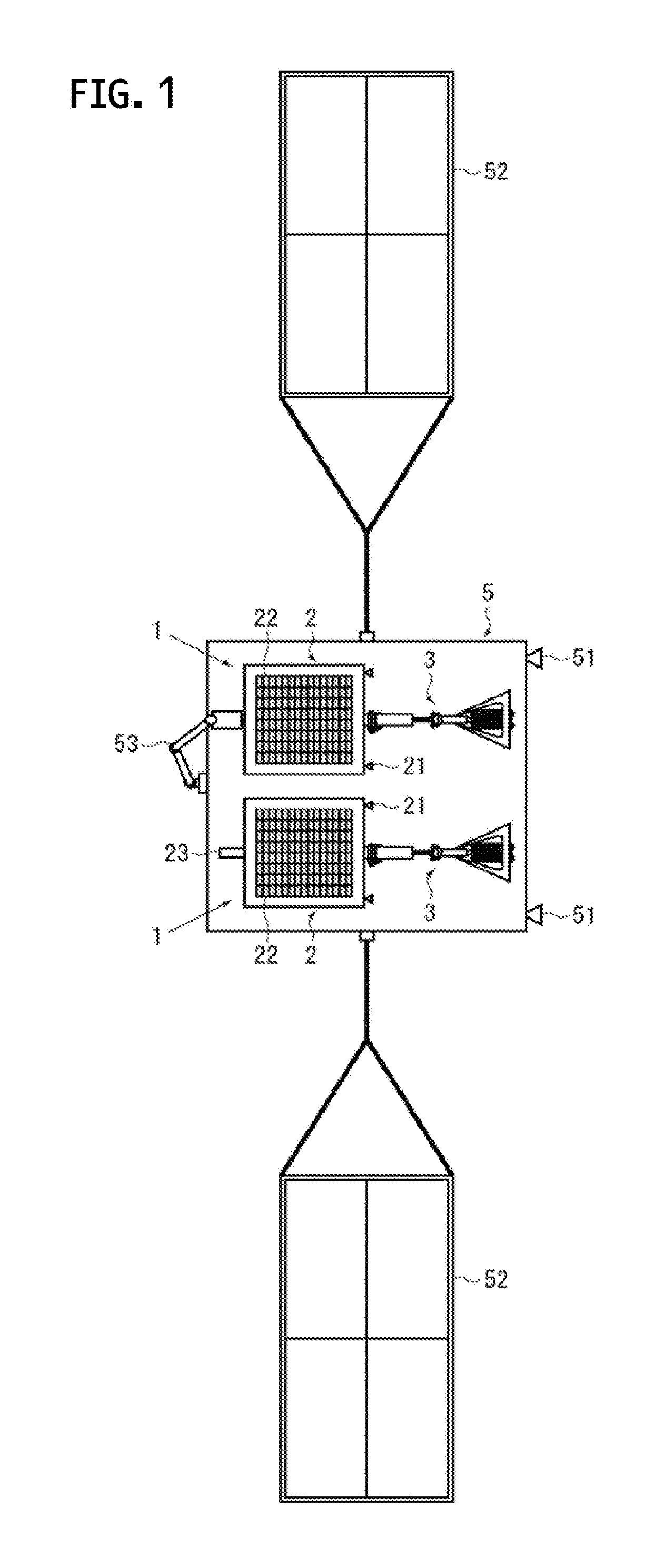
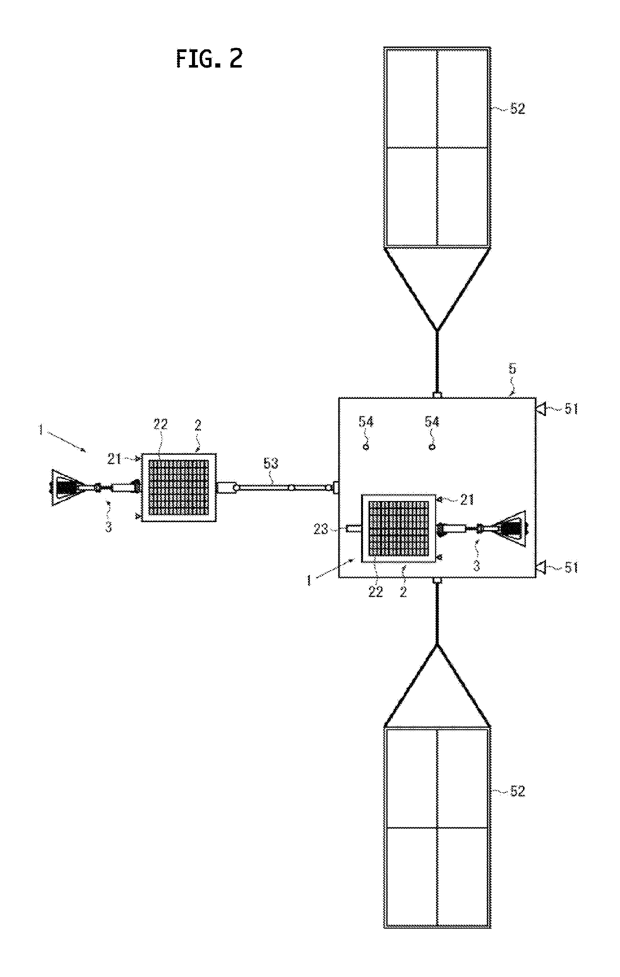
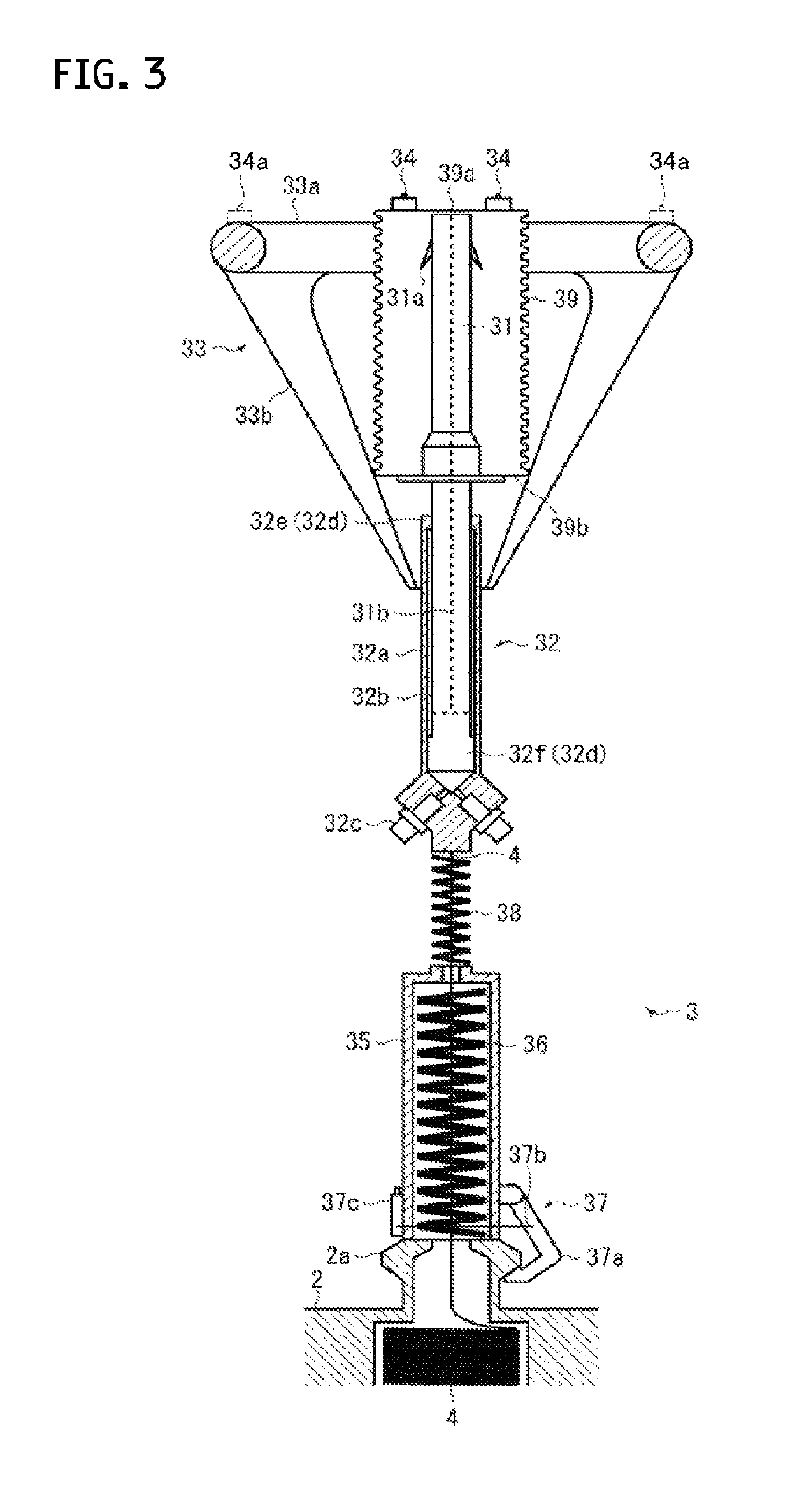
[0022]Hereinafter, several embodiments of the present disclosure are described by using FIGS. 1 to 10. Here, FIG. 1 is a top view showing debris removal devices according to the present disclosure, showing a state where the debris removal devices are accommodated in a mother ship. FIG. 2 shows a state where a debris removal device shown in FIG. 1 is assuming a capturing attitude. FIG. 3 is a partial lateral cross-sectional view showing a debris capture device of a debris removal device shown in FIG. 1.
[0023]A debris removal device 1 according to a first embodiment of the present disclosure is a device that captures debris drifting in outer space, and removes the debris from orbit. As shown in FIGS. 1 to 3, the debris removal device 1 includes: an end mass 2 adapted to be capable of approaching debris X to be removed; a debris capture device 3 separably-mounted on the end mass 2; and a tether 4 connecting the debris capture device 3 and the end mass 2 to each other. The debris captur...
second embodiment
[0059]In the second embodiment shown in FIGS. 8A and 8B, the end mass 2 includes a support device 24 that supports the shooting device 32. The support device 24 includes, for example, a pair of frames 24a each rotatably-connected to the end mass 2 via a hinge 24c, and a restraining device 24b that restrains the front end portions of both of the frames 24a to the shooting device 32.
[0060]The pair of frames 24a are provided at positions facing each other, with the shooting device 32 interposed therebetween, and holding the shooting device 32 therebetween. Each of the frames 24a has, for example, an A-letter shape as shown in FIG. 8B, and two-leg portions are each connected to the end mass 2. The restraining device 24b includes, for example, a wire that restrains the front end portions of the pair of frames 24a in a state of being in contact with the shooting device 32 (specifically, the cylinder 32a), and a wire cutter that cuts the wire. Note that the shape of the frames 24a and the ...
third embodiment
[0063]In the third embodiment shown in FIG. 9A, a buffer 6 is provided which reduces the impact generated when the debris capture device 3 comes into contact with the surface of the debris X. The buffer 6 is provided, for example, at an intermediate portion of a tubular body constituting the tether release port 2a of the end mass 2, and includes a link mechanism, for example. The link mechanism links a front section and a rear section formed by, for example, dividing the tubular body of the tether release port 2a into two front and rear pieces. Here, the buffer 6 is shown which includes the two links, but the number of the links is not limited to that shown in the drawing. In addition, the buffer 6 may be one utilizing an elastic body such as a spring or rubber, or a component such as a bellows instead of the link mechanism.
[0064]In reference to the debris removal device 1 according to the third embodiment, for example, the frames 24a can be retracted at a stage of the approaching s...
PUM
 Abstract
Description
Claims
Application Information
 - R&D
- Intellectual Property
- Life Sciences
- Materials
- Tech Scout
- Unparalleled Data Quality
- Higher Quality Content
- 60% Fewer Hallucinations
Browse by: Latest US Patents, China's latest patents, Technical Efficacy Thesaurus, Application Domain, Technology Topic, Popular Technical Reports.
© 2025 PatSnap. All rights reserved.Legal|Privacy policy|Modern Slavery Act Transparency Statement|Sitemap|About US| Contact US: help@patsnap.com


