External fixation for the correction of bone deformity and trauma

a bone deformity and external fixation technology, applied in the field of external bone fixation system for the treatment of bone deformity and trauma, can solve the problems of inconvenient movement, minimal or no weight bearing capacity, and uncomfortable current system for patients, so as to improve the patient's comfort and stability, facilitate the access to the limb, and stabilize the fixation point

Active Publication Date: 2019-09-17
NEW STANDARD DEVICE LLC
View PDF6 Cites 6 Cited by
  • Summary
  • Abstract
  • Description
  • Claims
  • Application Information

AI Technical Summary

Benefits of technology

[0004]Fixation plates are coupled with either posts, rods or telescoping struts and may include bridges to provide strength and stability. The disclosed technology enables ring-like fixation with stable point of fixation while leaving an opening to allow for edema and easier access to the limb under treatment. Different plates may be selected by a Hea

Problems solved by technology

Current systems are both uncomfortable for the patient and inconvenient when a wound is cleaned.
In addition, current EBF systems for acute trauma may only provide a t

Method used


Image

  • External fixation for the correction of bone deformity and trauma
  • External fixation for the correction of bone deformity and trauma
  • External fixation for the correction of bone deformity and trauma

Examples


Embodiment Construction

[0025]The illustrations and diagrams in the Figures illustrate the architecture, functionality, and operation of possible implementations of systems according to various embodiments of the present invention.

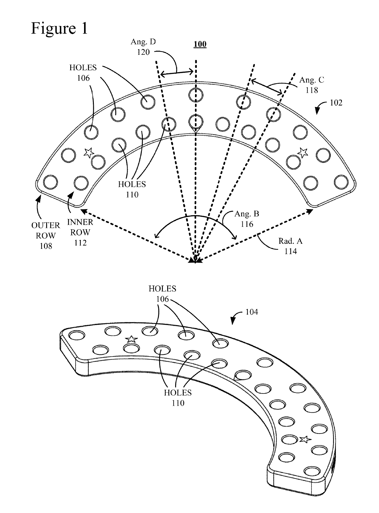
[0026]FIG. 1 is an illustration of two views of one embodiment of that which the Inventors have defined as a C Plate 100. C Plate 100 is illustrated from two (2) different angles, i.e., a top view 102 and a perspective view 104. C Plate 100 is typically employed to conform to a patient's extremity, or limb.

[0027]C Plate 100 has a semi-circular curvature that may follow the arc of a circle. C Plate 100 includes a row of holes 106, i.e. forming an outer row 108, and a row of holes 110, i.e., forming an inner row 112. For the sake of simplicity, only three holes in each of rows 108 and 112 are labeled. Rows 108 and 112 follow the curvature of C Plate 100. In this example, C Plate 100 covers an angle, or an Angle (Ang.) B 116, equal to approximately one hundred thirty-eight degrees (...


PUM


Abstract

Provided is an apparatus and component parts of a system for the external fixation of bones. The component parts include fixation plates such as a C Plate, a N Plate, a J Plate, an I Plate and a K Plate. Two or more fixation plates are configured along an axis, the two or more fixation plates selected from a list, the list comprising a plurality of C Plates; a plurality of N Plates; a plurality of J Plates; and a plurality of I Plates; a plurality of telescoping adjustable struts that connect a first fixation plate along the axis with a second fixation plate of the plurality of fixation plates along the axis, wherein the first and second fixation plates are adjacent plates along the axis; and a plurality of posts, each post connecting two adjacent fixation plates of the plurality of fixation plates along the axis.

Description

FIELD OF DISCLOSURE[0001]The claimed subject matter relates to an external bone fixation system for the treatment of bone deformity and trauma.BACKGROUND OF THE INVENTION[0002]Current External Bone Fixation (EBF) systems for the treatment of bone deformity and acute trauma employ circular rings that surround a patient's limb. Typically, the diameter of such rings must be approximately four centimeters (4 cm) larger than the limb being treated to allow for swelling in the limb. Oversized rings to accommodate large extremities may also be used. Current systems are both uncomfortable for the patient and inconvenient when a wound is cleaned. One well-known reconstructive system is the Ilizarov frame, as shown in U.S. Pat. Nos. 4,365,624; 4,615,338; 4,978,348; 5,702,389 and 5,971,984. The Ilizarov frame uses a combination of circular frames, pins and wires for deformity correction. In addition, current EBF systems for acute trauma may only provide a temporary fix until a definitive treat...

Claims


Application Information

Patent Timeline
IPC IPC(8): A61B17/64A61B17/62A61B17/56A61B17/00
CPCA61B17/62A61B17/6433A61B2017/00477A61B2017/568A61B2017/00991A61B17/645A61B17/6425
Inventor KLEIN, JR., C. DOUGLASWIGGINTON, ROBERT E.PHAMVU, BRYANT T.
Owner NEW STANDARD DEVICE LLC
Why Eureka
Try Eureka