
Self-aligning corner bead for fireproofing structural steel member and method of using same

a technology of fireproofing structural steel and corner bead, which is applied in the direction of fireproofing, girders, transportation and packaging, etc., can solve the problems of difficult alignment of the corner bead with the adjacent surface, difficulty in properly adjusting the traditional corner, and great skill in installing the corner bead for fireproofing structural steel

Active Publication Date: 2019-09-17
MILLER PHILIP GLEN
View PDF83 Cites 2 Cited by
  • Summary
  • Abstract
  • Description
  • Claims
  • Application Information

AI Technical Summary

Benefits of technology

The present invention provides an improved corner bead for fireproofing structural steel that does not require adjusting the legs. The width of the first wing provides a flat portion of metal grid through which fasteners attach the mesh to the lath disposed over the structural steel at the appropriate location. This easy application automatically aligns the mesh and eliminates the cumbersome process of adjusting the distance between the legs of traditional beads.

Problems solved by technology

Using this technique, the alignment of the corner bead with the adjacent surface is difficult and great skill is required to install the corner bead for fireproofing structural steel.
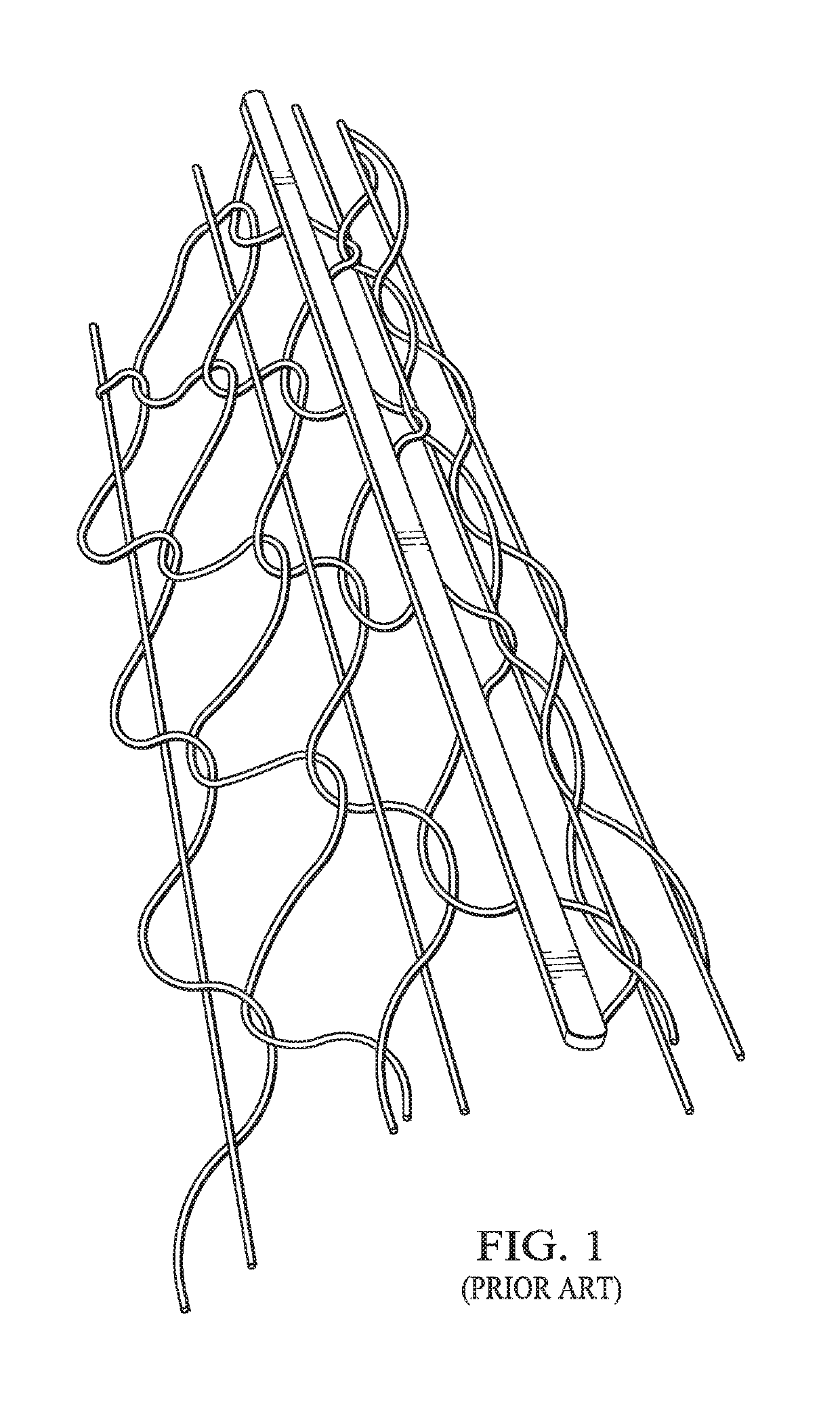
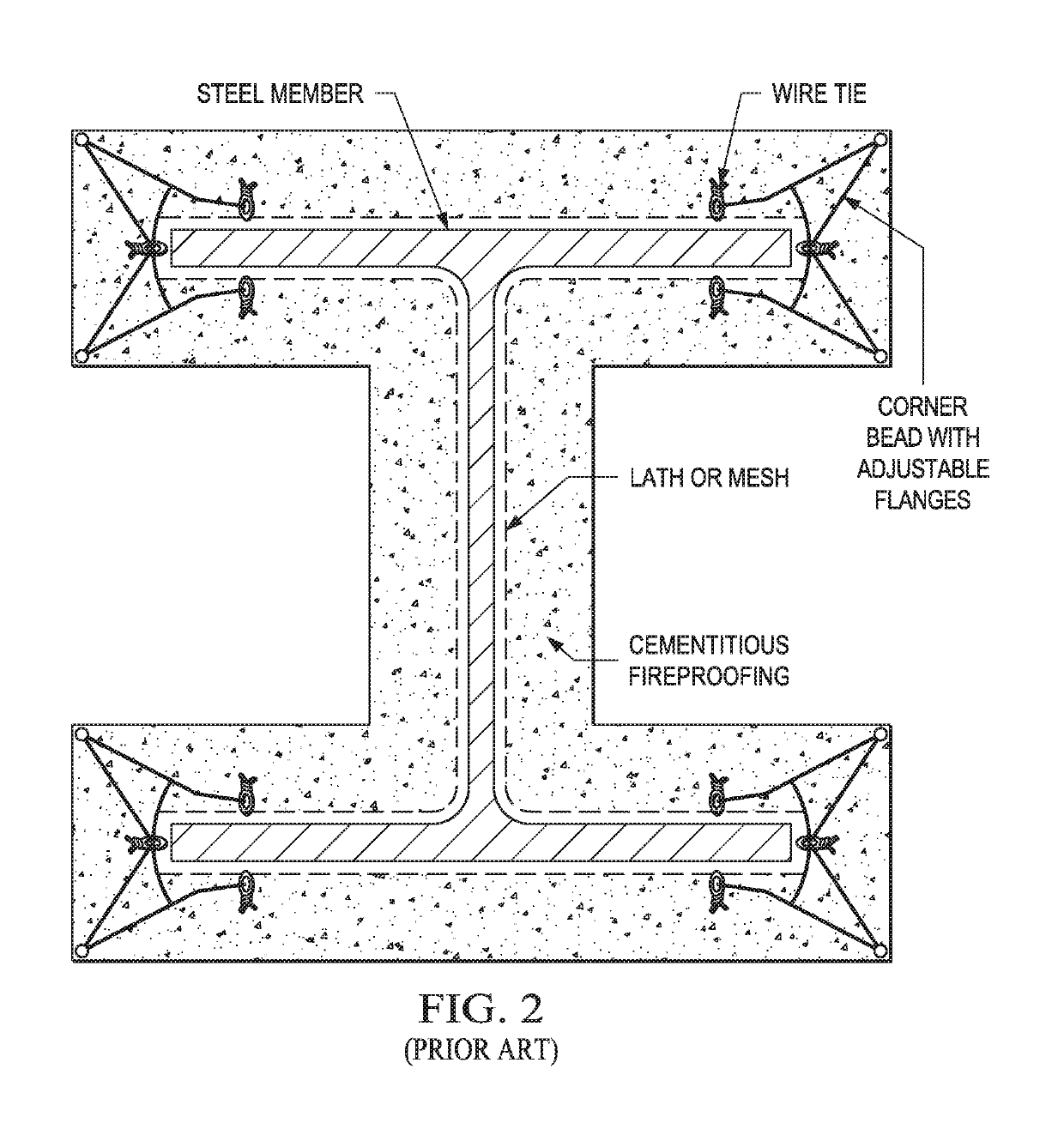
The prior art includes many problems, including the difficulty of properly adjusting the traditional corner bead to the adjacent surface, the uneven application of fireproofing material, and the lack of a dam for the wet cement material.
Despite these well-known and long-existing problems, and a readily apparent market for a solution, the prior art does not disclose or suggest a viable, cost-effective solution to the aforementioned problems of the prior art.
Applicant's approach to the problem described above is certainly simple, but it is equally unobvious.
Despite these well-known and long-existing problems, and a readily apparent market for a solution, no one has presented a viable, cost-effective solution such as applicant here provides.

Method used


Image

  • Self-aligning corner bead for fireproofing structural steel member and method of using same
  • Self-aligning corner bead for fireproofing structural steel member and method of using same
  • Self-aligning corner bead for fireproofing structural steel member and method of using same

Examples


Embodiment Construction

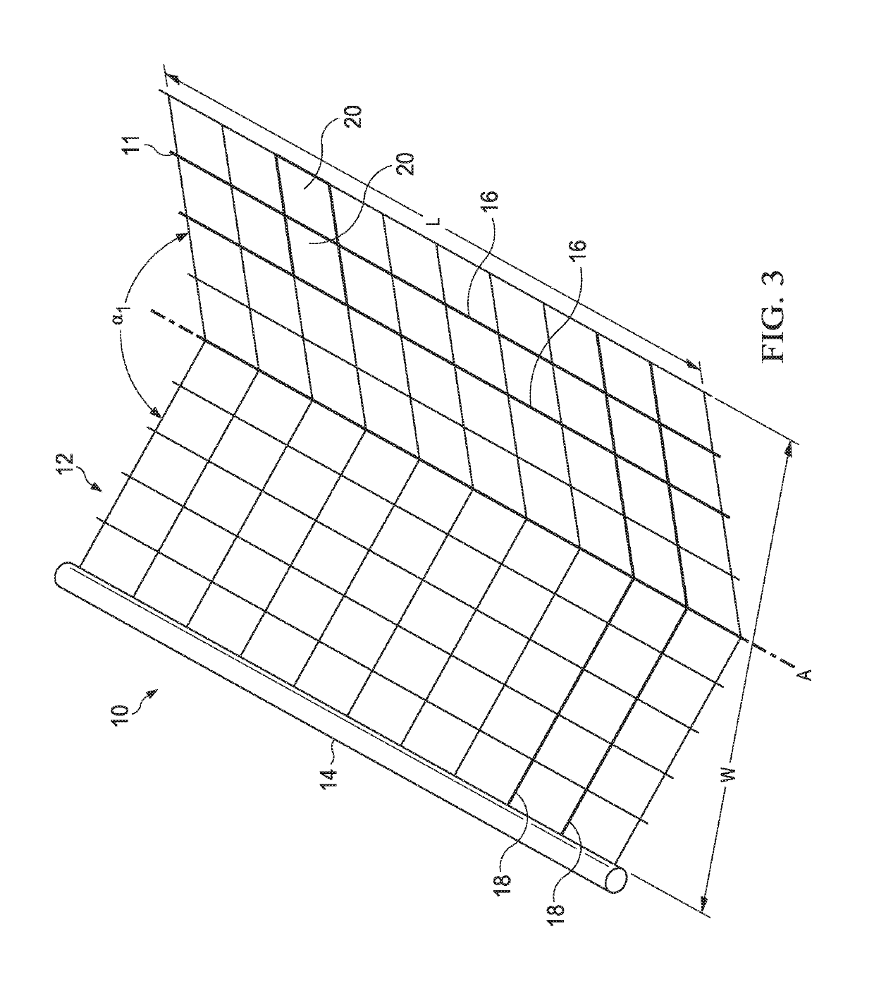
[0044]Referring to FIG. 3, corner bead 10 includes a plurality of longitudinal ribs 16 arranged substantially parallel with respect to a plurality of longitudinal axes, including longitudinal axis A and to each other, and a plurality of transverse ribs 18 distributed between and extending substantially perpendicular to the plurality of longitudinal axes and the plurality of longitudinal ribs 16. A set of void areas 20 is defined by the plurality of longitudinal ribs 16 and the plurality of transverse ribs 18, such that each void area 20 is bounded by at least two longitudinal ribs 16 and at least two transverse ribs 18. A section of corner bead 10 includes a single strip of welded wire fabric cut to a predetermined length L and a predetermined width W. The predetermined length L and the predetermined width W correspond to a predetermined fireproofing thickness.

[0045]In a preferred embodiment, corner bead 10 is made of a suitable metal, such as 16 gauge wire. Other suitable materials...


PUM


Abstract

A self-aligning corner bead for fireproofing structural steel, having a strip of welded wire fabric cut to the appropriate width for the fireproofing thickness and bent longitudinally to form an obtuse V-shaped device is disclosed. A plastic nosing is installed along one edge. A method of finishing the corners for fireproofing of structural steel member using an improved corner bead includes the step of attaching the first wing of an obtuse V-shaped device through a lathe to the structural steel member utilizing pneumatic or screw type fasteners. The mesh structure of the second wing of the V-shaped device provides a dam to form a roughened surface on the first application of fireproofing material until it hardens.

Description

CROSS-REFERENCE TO RELATED APPLICATIONS[0001]This application is a continuation application of U.S. application Ser. No. 15 / 382,687, filed Dec. 18, 2016, which is a continuation of U.S. application Ser. No. 14 / 832,074, filed Aug. 21, 2015, now U.S. Pat. No. 9,540,813, issued Jan. 10, 2017, which claims priority to U.S. Provisional Application No. 62 / 040,182, filed Aug. 21, 2014. U.S. application Ser. No. 14 / 832,074 is also a continuation-in-part of U.S. application Ser. No. 14 / 292,881, filed May 31, 2014, now U.S. Pat. No. 9,140,005, issued Sep. 22, 2015, which claims priority to U.S. Provisional Application No. 61 / 830,257, filed Jun. 3, 2013. Each of the above patent applications is incorporated by reference herein in its entirety to provide continuity of disclosure.TECHNICAL FIELD[0002]The present invention relates generally to a corner bead for cementitious fireproofing of structural steel members and, more particularly, to a device that is self-aligning in installation and allow...

Claims


Application Information

Patent Timeline
Patent Type & Authority Patents(United States)
IPC IPC(8): E04B1/94E04C3/06E04C3/293E04F13/04E04F13/06E04C3/04
CPCE04C3/293E04B1/944E04C3/06E04C2003/0452Y10T428/1241E04F13/047E04F13/068E04F13/06
Inventor MILLER, PHILIP GLEN
Owner MILLER PHILIP GLEN
Learn More