Fuel injector repair tool

a technology for fuel injectors and repair tools, which is applied in the direction of fuel injection apparatus, machine/engines, feed systems, etc., can solve the problems of increasing the time and cost of replacing the fuel injector, the method has its own problems, and the tool can damage or get stuck in the mounting hole, so as to reduce the risk of damage to the mounting valve cover, the mounting hole, and the cylinder head. , the effect of reducing the time and cost of repairs

Inactive Publication Date: 2019-09-17
PROMAX LLC
View PDF5 Cites 5 Cited by
  • Summary
  • Abstract
  • Description
  • Claims
  • Application Information

AI Technical Summary

Benefits of technology

[0007]Embodiments of the disclosed invention avoid or minimize some of these issues by facilitating the removal of the fuel injector while the cylinder head assembly and mating components remain fixed in the vehicle and without the need to screw any tools into the mounting holes or to secure them to the cylinder head. This invention avoids the dangers of threading and unthreading a tool into the mounting hole and cylinder head and can allow the assembly to be repaired in an even shorter amount of time, which reduces the time and cost of repairs and minimizes the risk of damaging the mounting valve cover, mounting hole, and cylinder head.

Problems solved by technology

This method has its own problems, however.
First, it requires passing the fuel injector removal tool through the hold-down bolt hole in the valve cover and threading and unthreading it into the threaded mounting hole in the cylinder head assembly, which creates an opportunity for the tool to damage or get stuck in the mounting hole.
Either problem will greatly increase the time and cost of replacing the fuel injector.
Second, the process is more time-consuming than it needs to be, because the fuel injector removal tool must pass through the valve cover injector mounting hole and then be screwed and unscrewed from the cylinder head.

Method used


Image

  • Fuel injector repair tool
  • Fuel injector repair tool
  • Fuel injector repair tool

Examples


Embodiment Construction

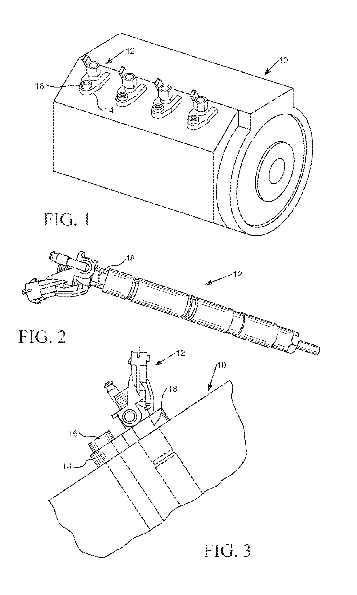
[0021]A diesel engine cylinder head assembly 10 is shown in FIG. 1. A fuel injector 12 passes through and into head assembly 10. Fuel injector 12 is secured onto head assembly 10 by a fuel injector hold-down fork 14, which has tines that fit around machined flats or grooves 18 in fuel injector 12 (as shown in FIGS. 1-3). Hold-down fork 14 is secured to head assembly 10 via a fuel injector hold-down bolt 16. Hold-down bolt 16 passes through fuel injector hold-down bolt hole 20 (shown in FIG. 8) and screws into a threaded mounting hole inside head assembly 10. Note that there is generally more than one fuel injector in a head assembly, so there will be multiple holes into which the fuel injectors and hold-down bolts are secured.

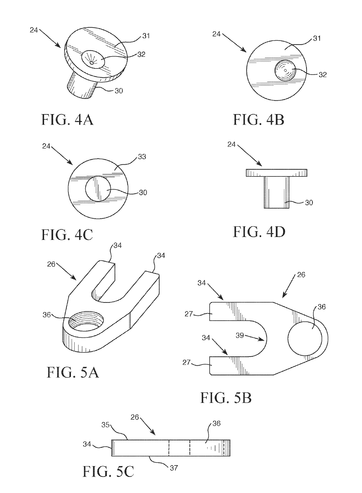
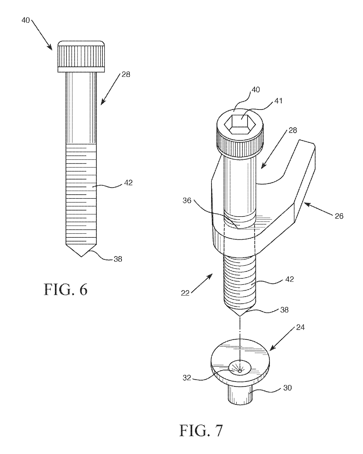
[0022]One embodiment of the present invention is shown in FIGS. 4-7. This embodiment is comprised of three discrete elements—a generally cylindrical plate 24, a threaded fork 26, and a lift bolt 28—and collectively plate 24, fork 26, and lift bolt 28 form a new...


PUM


Abstract

A tool for removing fuel injectors from a head assembly is disclosed that is comprised of a bolt, a dual-tined fork, and a plate that fit into the existing hold-down bolt holes in a head assembly and grooves in the fuel injectors.

Description

[0001]This application claims the benefit of U.S. Provisional Patent Application No. 62 / 488,111, filed on Apr. 21, 2017, the contents of which are hereby incorporated herein by reference.FIELD OF THE INVENTION[0002]The present invention generally relates to an apparatus for removing a fuel injector from a cylinder head assembly in an engine.BACKGROUND OF THE INVENTION[0003]Modern gas and diesel internal combustion engines require precise control of fuel delivery to a combustion chamber in order to operate at peak performance (such as efficiency, power, reliability, etc.). This fuel control is typically accomplished via a fuel injector, which provides a mechanism for reliably and accurately injecting fuel into the combustion chamber of internal combustion engine, such as one found in automotive and truck engines, for example. Fuel injectors require frequent service to operate efficiently in dispersing precise amounts of fuel into the combustion chamber. The life cycle of the fuel inj...

Claims


Application Information

Patent Timeline
Patent Type & Authority Patents(United States)
IPC IPC(8): F02M61/14B25B27/00B25B27/02
CPCB25B27/0035F02M61/14B25B27/023F02M2200/856F02M2200/855
Inventor DEL ROSSA, JEFFREY
Owner PROMAX LLC
Why Eureka
Try Eureka