Conical access split magnet system

a split magnet and conical access technology, applied in the direction of superconducting magnets/coils, magnetic measurements, instruments, etc., can solve the problems of limiting the rectangular geometry of the coil, still generally deficient, etc., and achieve the effect of improving optical access

Active Publication Date: 2019-09-17
QUANTUM DESIGN
View PDF22 Cites 0 Cited by
  • Summary
  • Abstract
  • Description
  • Claims
  • Application Information

AI Technical Summary

Problems solved by technology

One of the challenges that faces the designer of such a magnet system is to achieve fields that are both high and that have a sufficiently large and accessible working region.
However, though the split coil arrangement provides the advantage of side access perpendicular to the field direction as indicated above, it is still generally deficient when used in applications requiring unimpeded access to the central field region with a large viewing angle, as the rectangular geometry of the coils is limiting.

Method used


Image

  • Conical access split magnet system
  • Conical access split magnet system
  • Conical access split magnet system

Examples


Embodiment Construction

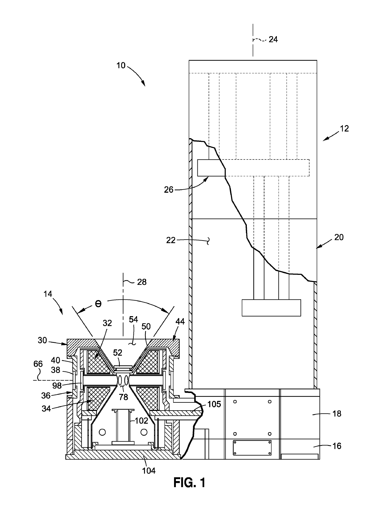
[0032]Referring now to the drawings for which the showings are for purposes of illustrating a preferred embodiment of the present disclosure only, and not for purposes of limiting the same, FIG. 1 depicts a cryostat apparatus 10 for providing a magnetic field. As will be explained in more detail below, the cryostat apparatus 10 includes a uniquely configured split coil magnet configuration, wherein each coil has a tapered surface to enhance the viewing angle in at least one viewing direction.

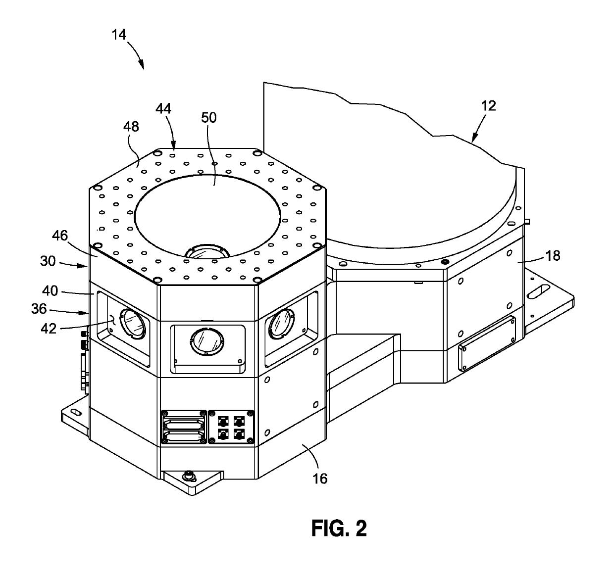
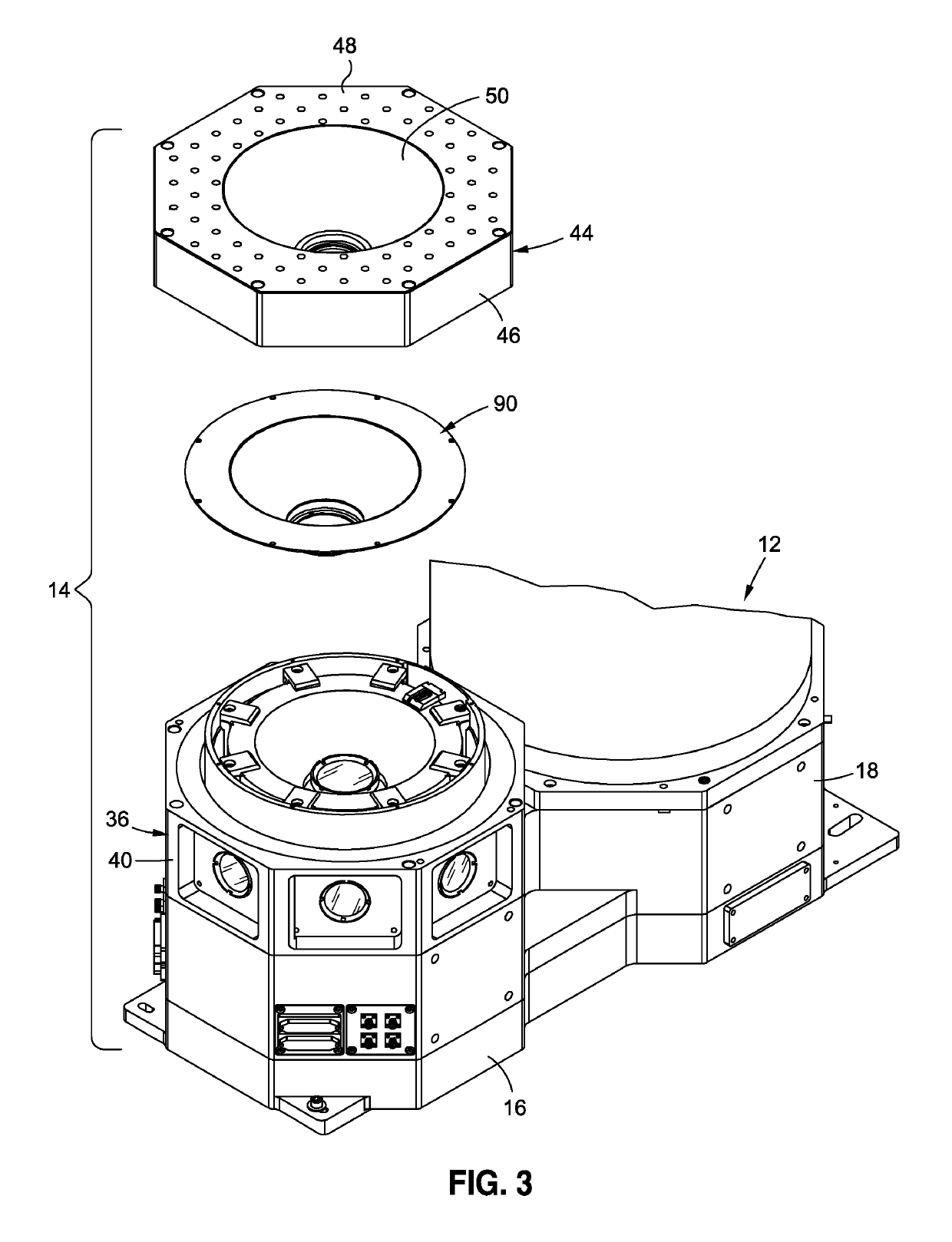
[0033]According to one embodiment, the cryostat apparatus 10 generally includes a cooler 12 and a magnet assembly 14 residing next to the cooler 12, with the cooler 12 being configured to provide cooling power to the magnet assembly 14. The cooler 12 and the magnet assembly 14 may be physically connected to each other at respective lower regions of both the cooler 12 and the magnet assembly 14. Along these lines, in the exemplary embodiment, the cryostat apparatus 10 includes a base 16, and a lo...


PUM

PropertyMeasurementUnit
temperatureaaaaaaaaaa
magnetic fieldaaaaaaaaaa

Abstract

A cryostat apparatus including a cooler configured to cool a cryogenic fluid. The cooler includes a cooler chamber disposed about a cooler axis. A magnet assembly is in thermodynamic communication with the cooler and is disposed about a magnet axis offset from the cooler axis. The magnet assembly includes a magnet housing and first and second annular magnet coils disposed about the magnet axis within the magnet housing. A viewing chamber is at least partially located between the first and second magnet coils, such that the magnet axis and a viewing axis perpendicular to the magnet axis both pass through the viewing chamber, with the viewing axis extending between the first and second magnet coils. The first annular magnet coil includes a first conical surface disposed about the magnetic axis and having minimum and maximum peripheries, the minimum periphery being disposed adjacent the viewing chamber.

Description

CROSS-REFERENCE TO RELATED APPLICATIONS[0001]Not ApplicableSTATEMENT RE: FEDERALLY SPONSORED RESEARCH / DEVELOPMENT[0002]Not ApplicableBACKGROUND1. Technical Field[0003]The present disclosure relates generally to magneto-optical property measurement devices and, more particularly, to a superconducting magnet design which is suitable for use in such devices and has a unique shape which presents advantages over existing designs when used in laboratory magnet systems requiring optical access.2. Description of the Related Art[0004]Superconducting magnets are typically used in laboratory environments where it is desired to expose specimens to fields larger than, for example, about three (3) Tesla. One of the challenges that faces the designer of such a magnet system is to achieve fields that are both high and that have a sufficiently large and accessible working region. These requirements have led to the widespread adoption of two main magnet geometries: (1) the single solenoid, and (2) th...

Claims


Application Information

Patent Timeline
Patent Type & Authority Patents(United States)
IPC IPC(8): G01R33/38G01R33/3815H01F6/04
CPCG01R33/3806G01R33/3815G01R33/3804H01F6/04
Inventor MARTIEN, DINESHNEILS, WILLIAMBLACK, RANDALL
Owner QUANTUM DESIGN
Why Eureka
Try Eureka