
Write and read common leveling for 4-bit wide DRAMs

a dram and leveling technology, applied in the field of integrated circuits, can solve the problems of adding complexity to the memory controller design, and different insertion delays between

Active Publication Date: 2019-09-17
MARVELL ASIA PTE LTD
View PDF24 Cites 6 Cited by
  • Summary
  • Abstract
  • Description
  • Claims
  • Application Information

AI Technical Summary

Benefits of technology

This patent is about a method for improving the performance of a memory controller. It describes a method for aligning data bits during a writing operation. By adjusting the timing of writing to the memory, the system can reduce errors and improve data reliability. This is achieved by using a deskew delay line which can be reused for different modes of operation and by optimizing the deskew settings of each data bit. Overall, this method simplifies the logic design and reduces the required resources for achieving both read and write leveling.

Problems solved by technology

For the case of a ×4 configuration, because there are two devices interfacing with the controller off-chip per byte, there will likely be different insertion delays between them.
This adds complexity to the memory controller design.

Method used


Image

  • Write and read common leveling for 4-bit wide DRAMs
  • Write and read common leveling for 4-bit wide DRAMs
  • Write and read common leveling for 4-bit wide DRAMs

Examples


Embodiment Construction

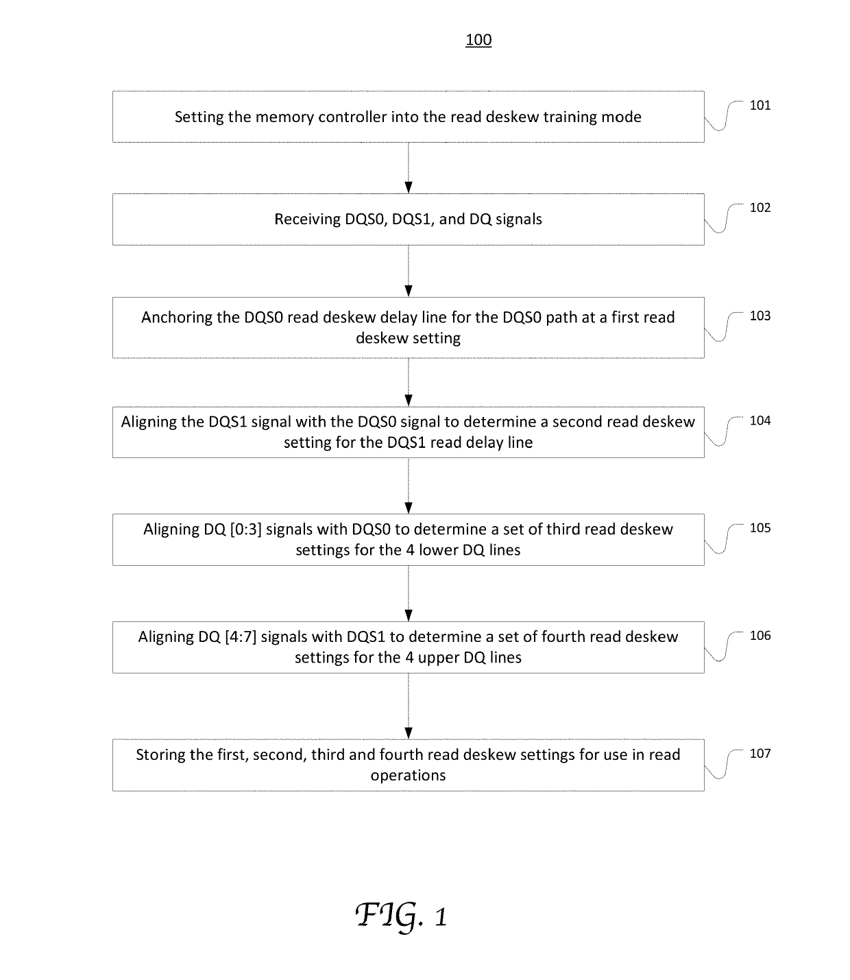
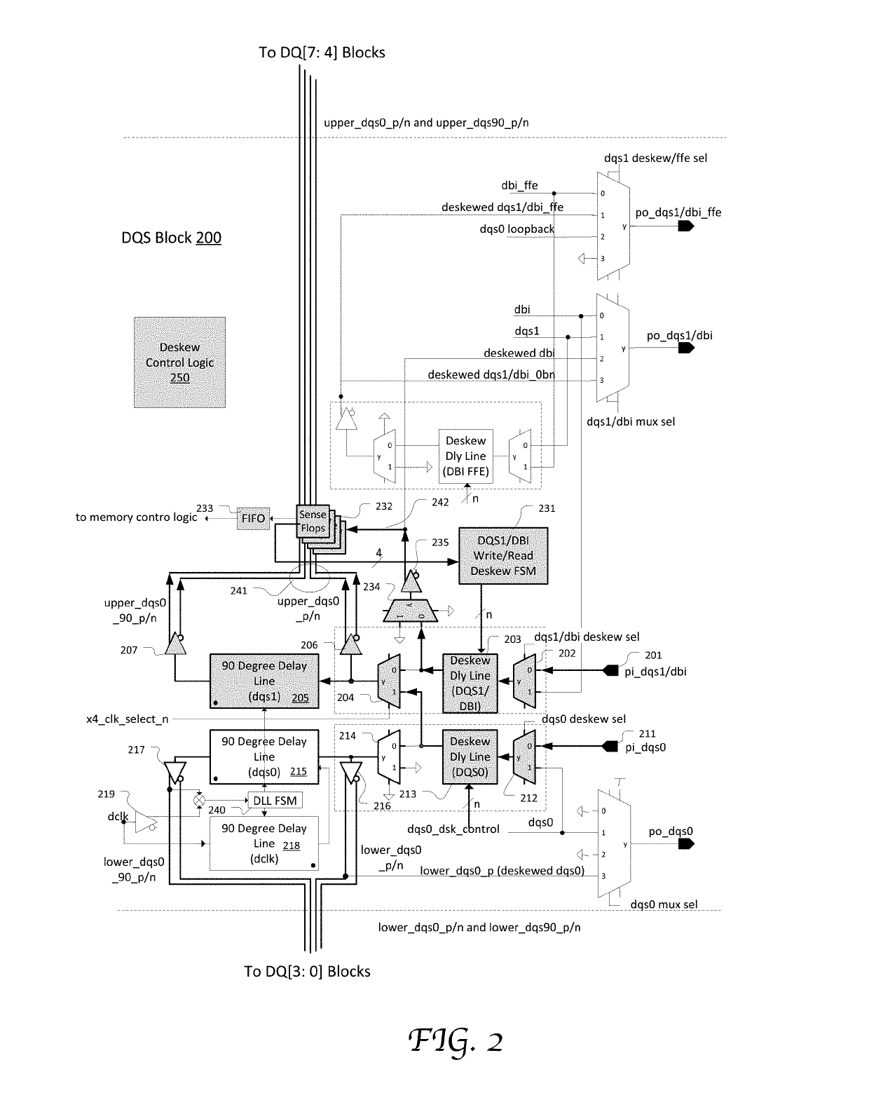
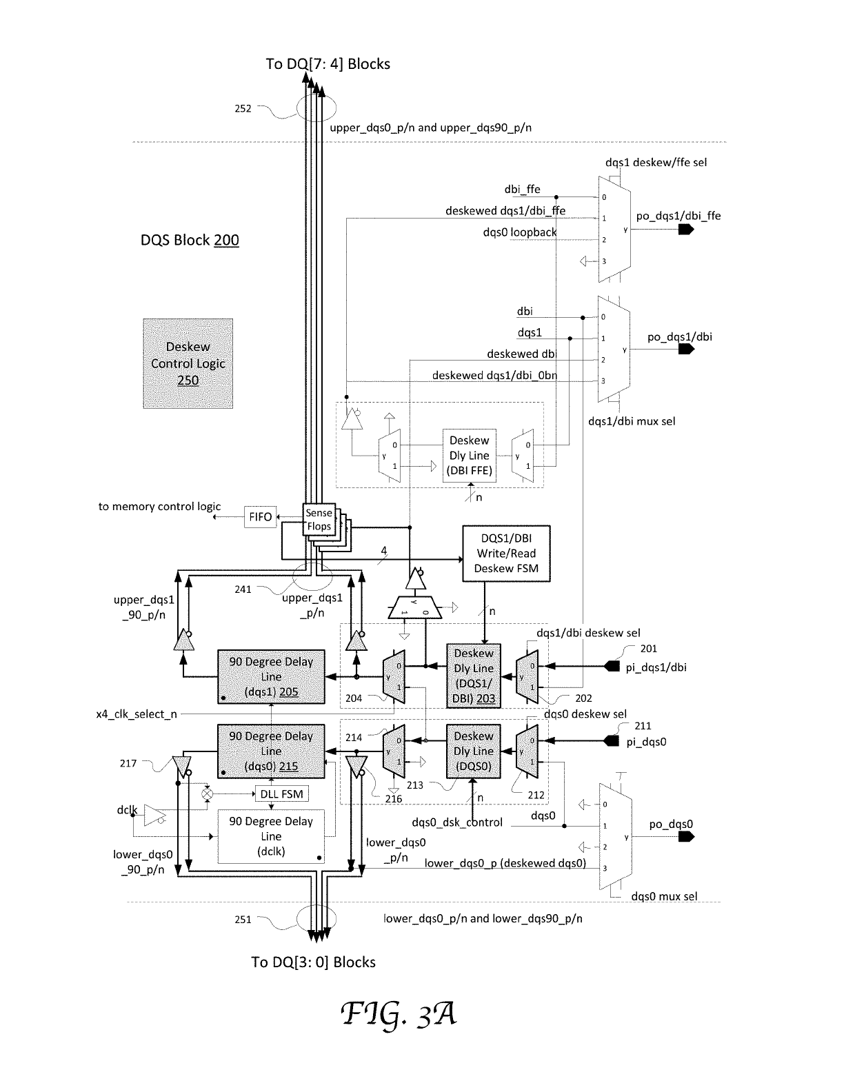
[0027]Reference will now be made in detail to the several embodiments of the present invention, examples of which are illustrated in the accompanying drawings. While the invention will be described in conjunction with these embodiments, it will be understood that they are not intended to limit the invention to these embodiments. On the contrary, the invention is intended to cover alternatives, modifications and equivalents, which may be included within the spirit and scope of the invention as defined by the appended claims. Furthermore, in the following detailed description of embodiments of the present invention, numerous specific details are set forth in order to provide a thorough understanding of the present invention. However, it will be recognized by one of ordinary skill in the art that the present invention may be practiced without these specific details. In other instances, well-known methods, procedures, components, and circuits have not been described in detail so as not ...


PUM


Abstract

System and method of write deskew training for ×4 mode memory control interface configurations. Write leveling logic in the memory controller is adjusted to obtain a write leveling setting for delaying both first and second strobe signals associated with a byte. The adjustment is based on feedback of first set of bits of a byte and irrespective of the feedback of the second set of bits of the byte. The write leveling logic is then anchored at the write leveling setting, and a deskew delay line for the second strobe signal is adjusted to obtain a first deskew setting based on the feedback of the second set of bits. Thus, in write operations, the write leveling setting can be common within the byte even the two strobe signals are transmitted to or received from two different memory storage devices.

Description

TECHNICAL FIELD[0001]Embodiments of the present invention are related to the field of integrated circuits, and in particular, to deskew mechanisms in memory controllers.BACKGROUND OF THE INVENTION[0002]In a typical synchronous dynamic random-access memory (SDRAM) design, each data byte (8 bits of data) of a ×8 SDRAM device or each nibble (4 bits of data) of a ×4 SDRAM device is associated with a dedicated data strobe (DQS). In a ×4 mode, two DQS signals (e.g., namely DQS0, DQS1) are used to clock one byte, and each DQS is associated with 4 data bits (DQs); whereas, in a ×8 mode, one DQS (e.g., namely DQS0) is associated with all 8 DQ bits in the byte. The ×4 mode thus requires an extra bidirectional data strobe signal, DQS1, to be sent between the memory controller and the memory. DQs and the differential data strobes (DQSs) are transported through bi-directional buses and are driven by the memory controller during a memory write and driven by the memory during a memory read.[0003]A...

Claims


Application Information

Patent Timeline
IPC IPC(8): G11C29/00G11C11/4094G11C11/4096G11C7/10G11C8/18
CPCG11C8/18G11C7/1063G11C11/4096G11C7/1093G11C29/842G11C11/4094G11C7/1048G11C7/109G11C2207/2254G11C29/023G11C29/028
Inventor LIN, DAVID DA WEI
Owner MARVELL ASIA PTE LTD
Learn More