

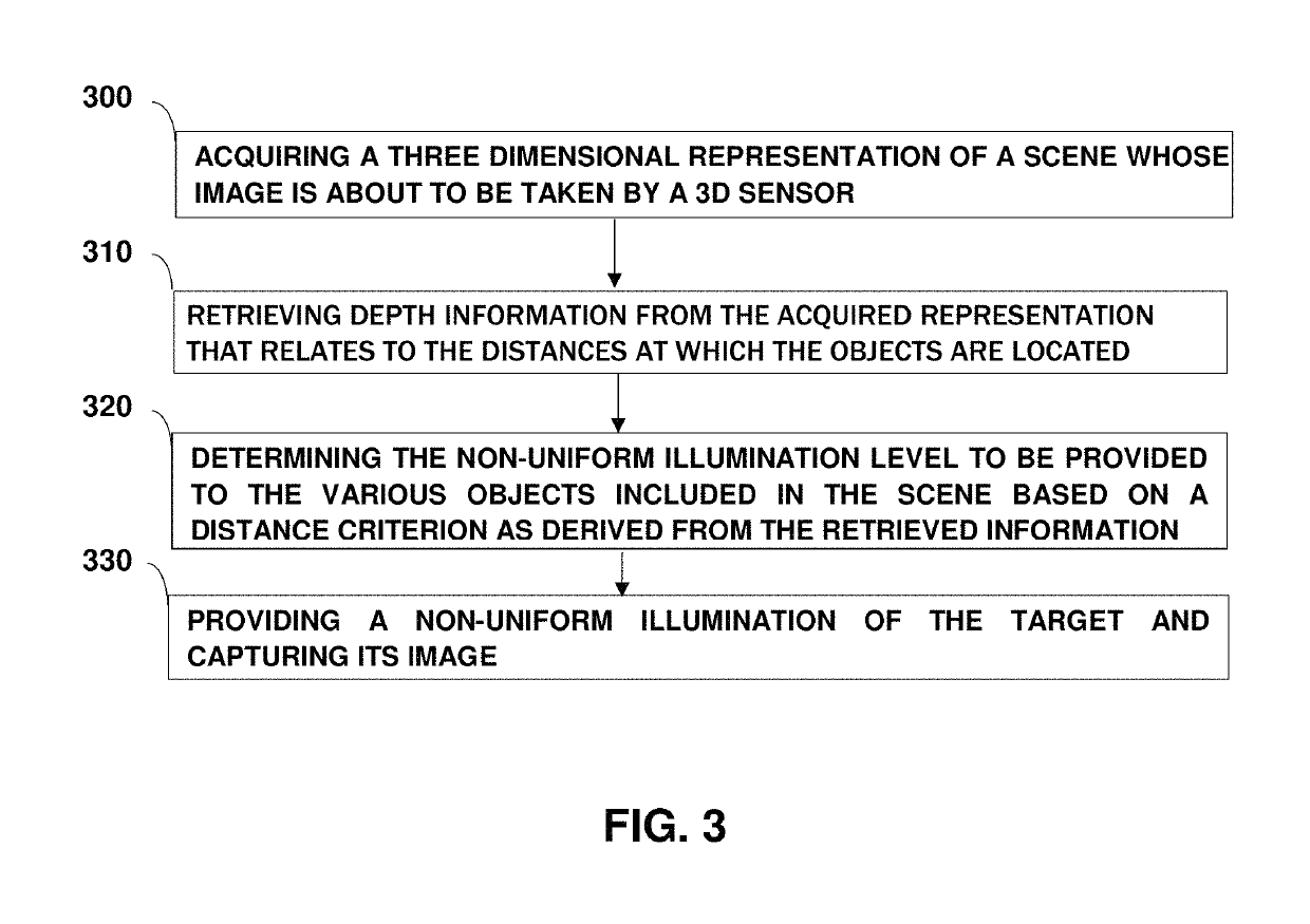
Illuminating a scene whose image is about to be taken
a scene and image technology, applied in the field of illumination, can solve the problems of insufficient ambient light, inability to automatically adjust the device based on detailed information, and overly bright faces, so as to prevent camera dazzling, and improve the effect of photography
- Summary
- Abstract
- Description
- Claims
- Application Information
AI Technical Summary
Benefits of technology
Problems solved by technology
Method used
Image

Examples
Embodiment Construction
[0045]In this disclosure, the term “comprising” is intended to have an open-ended meaning so that when a first element is stated as comprising a second element, the first element may also include one or more other elements that are not necessarily identified or described herein, or recited in the claims.
[0046]In the following description, for the purposes of explanation, numerous specific details are set forth in order to provide a better understanding of the present invention by way of examples. It should be apparent, however, that the present invention may be practiced without these specific details and that the invention is not limited to the scope of these examples.
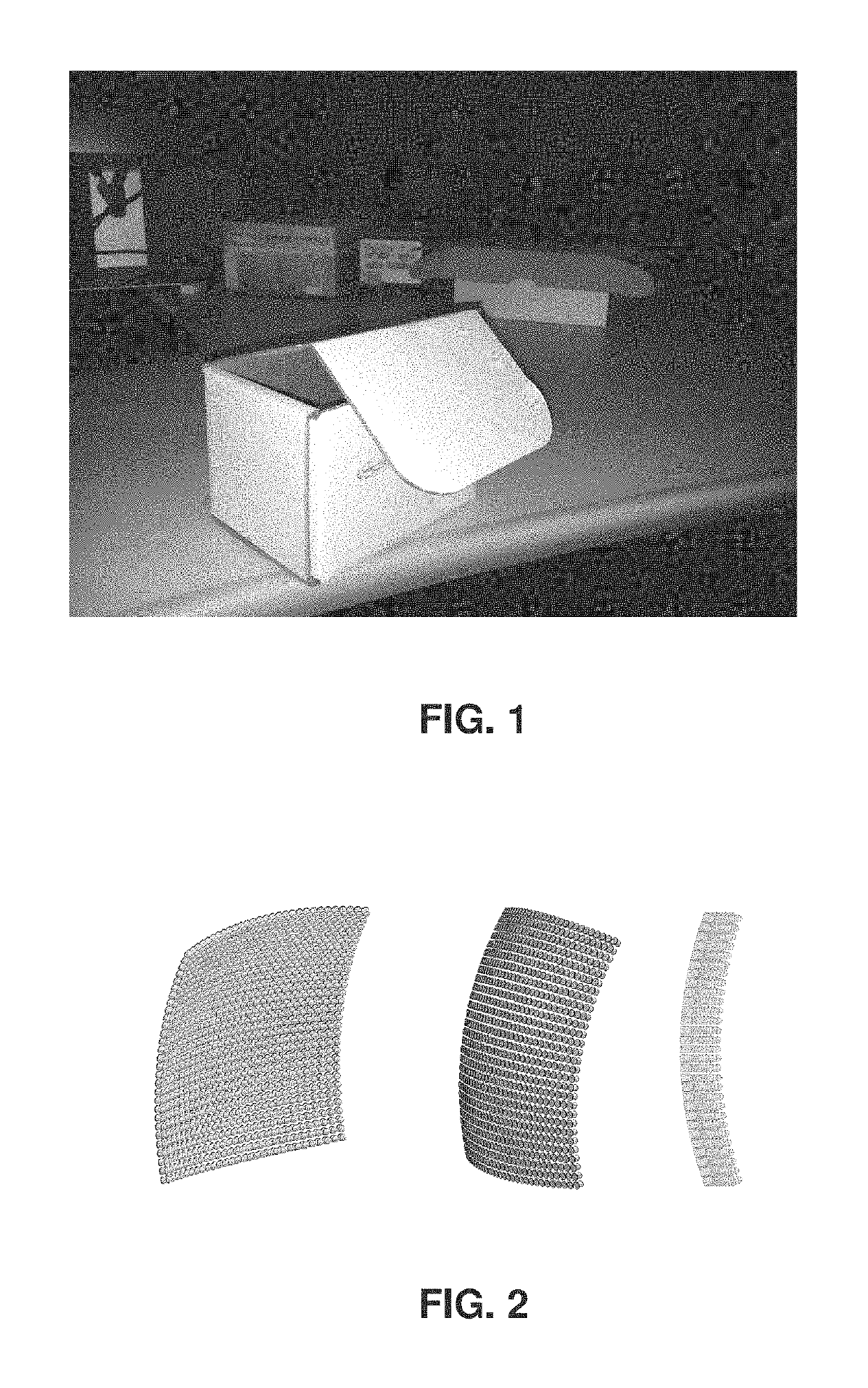
[0047]Under certain conditions, especially when taking photographs at relatively close distances while using flash light, close objects appear overexposed (too bright), while far objects may appear too dark). The reason being that the amount of light received by the camera from an object when the latter is illuminated...
PUM
 Abstract
Description
Claims
Application Information