Cleaning system for paint particles

a technology for cleaning systems and paint particles, applied in the direction of colloidal chemistry, filtration separation, separation processes, etc., can solve the problems of no longer performing the function of separation structures, heavy loading on cleaning modules, and collapse of separation structures present therein under their own weight, so as to facilitate storage and transport of separation structures. , the effect of reducing volum

Active Publication Date: 2019-10-22
BRAIN FLASH PATENTENTWICKLUNGS
View PDF26 Cites 7 Cited by
  • Summary
  • Abstract
  • Description
  • Claims
  • Application Information

AI Technical Summary

Benefits of technology

[0013]That permits accurate matching of the cleaning module to the soiling involved in the air flow (particle size, degree of moisture). That also permits selective swapping of successively arranged cleaning modules, which is advantageous as separation structures which are optimized for various particle sizes reach their capacity limit at different rates.
[0014]It is further advantageous that the selective swappability of the cleaning modules means that stockkeeping is necessary to a lesser degree.
[0015]For a good fit of the cleaning sub-structures in the hollow body, in a view along an axis which is substantially parallel to air flow in the condition of being arr

Problems solved by technology

Particularly when the cleaning modules are disposed in the floor of the spray booth, that results in a heavy loading on the cleaning module which is made from cardboard.
In the case of cleaning modules

Method used


Image

  • Cleaning system for paint particles
  • Cleaning system for paint particles
  • Cleaning system for paint particles

Examples


Embodiment Construction

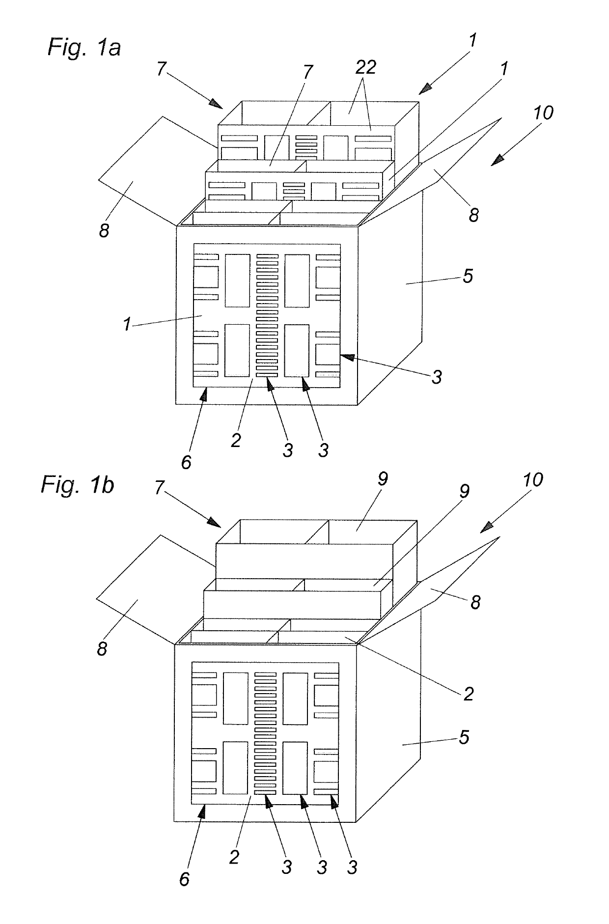
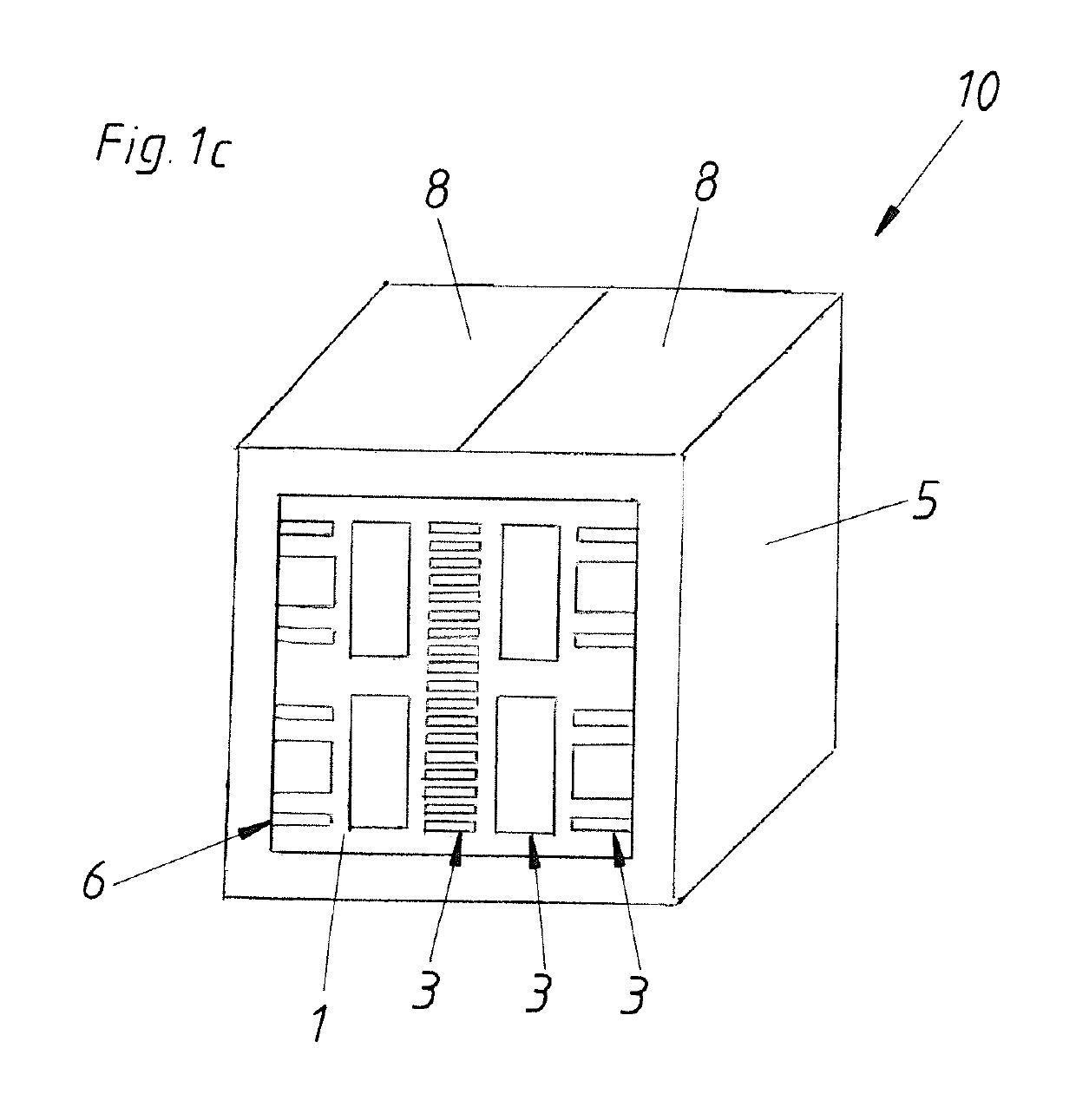
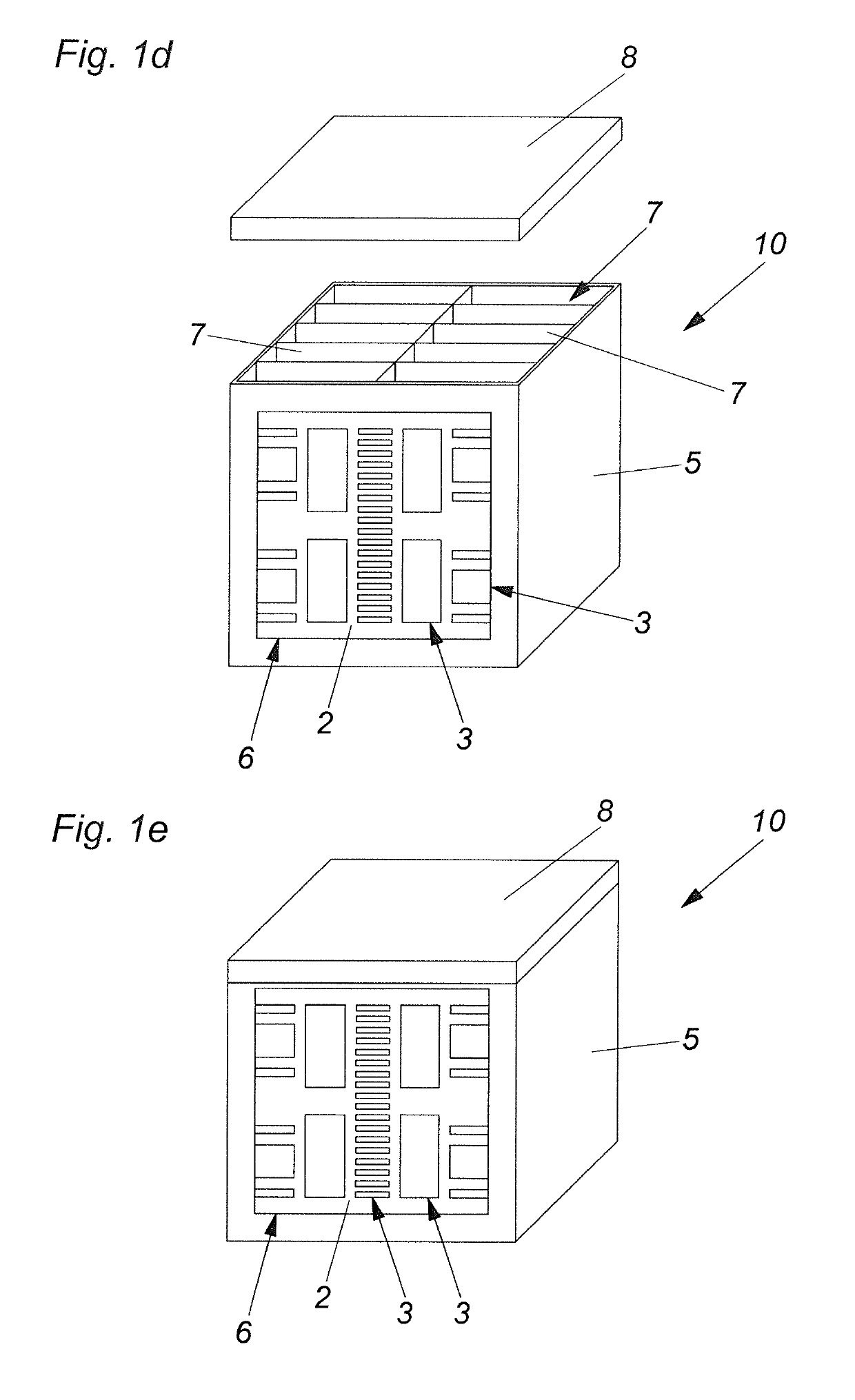
[0030]The cleaning module 10 shown in FIG. 1a firstly includes a hollow body 5 as well an intake opening 6 for the intake of the air flow to be cleaned. As the outlet opening is arranged on the rear of the hollow body 5 it cannot be seen in these views. The outlet opening has a substantially similar configuration to the intake opening 6.

[0031]The hollow body 5 has opening elements 8 which are in the form of opening flaps. In the present view, they are opened so that there is a clear view on to the interior of the hollow body 5. FIG. 1a shows a plurality of cleaning sub-structures 7 which in this case are all in the form of separation structures 1. The separation structures 1 have baffle walls 2 provided with openings 3. For the sake of clarity, not all baffle walls 2 and all openings 3 are provided with reference numerals as they are in part present as a multiplicity thereof.

[0032]FIG. 1b is similar to FIG. 1a except for the difference that two of the cleaning structures 7 are in th...


PUM

PropertyMeasurementUnit
Flow rateaaaaaaaaaa
Structureaaaaaaaaaa
Sizeaaaaaaaaaa

Abstract

A cleaning module for cleaning an air stream includes a hollow article which has an inlet port for the entry of the air stream to be cleaned and an outlet port for the exit of the cleaned air stream. A cleaning structure is provided for cleaning the air stream by particle separation and/or for filtration of the air stream. The cleaning structure has at least two separate cleaning sub-structures which through an opening element in the hollow article can be removed from the hollow article and/or can be arranged inside the hollow article.

Description

BACKGROUND OF THE INVENTION[0001]The present invention concerns a separation structure for cleaning an air flow, a cleaning module for cleaning an air flow, a set and an insertion frame.[0002]The modular arrangement of filter modules of cardboard is known from WO 03 / 084638 A2. The modules serve for the separation of paint particles or paint mist (overspray) from an exhaust air from a spray booth in which, for example, parts for a motor vehicle are being painted.[0003]It is noteworthy in that respect that a very large number of various paints is used. As a result, the exhaust air from spray booths contains widely varying kinds of paint impurities which, for example, are distinguished by particle size and moisture content. For relatively small dry particles, labyrinths with small openings and severe deflection configurations have to be provided for separation purposes so that due to their inertia (or due to centrifugal force) the particles are stopped at deflecting baffle walls of the...

Claims


Application Information

Patent Timeline
IPC IPC(8): B01D45/00B01D45/08B01D50/00B05B14/40B01D39/16B01D39/18B01D46/00
CPCB01D50/002B01D45/08B05B14/40Y10S55/31B01D39/16B01D39/18B01D46/0002B01D46/0016B01D46/406B01D50/20
Inventor GAVRAN, JADRANKOEDER, MICHAEL
Owner BRAIN FLASH PATENTENTWICKLUNGS
Why Eureka
Try Eureka