
Rapid diagnostic test device and sampling method using driven flow technology

a technology of driven flow and applied in fluid controllers, laboratory glassware, instruments, etc., can solve the problems of insufficient accuracy of many rapid in vitro diagnostics (ivd) test devices, no objective quantitative measure, and overall higher sensitivity and specificity

Active Publication Date: 2019-10-22
DNT SCI RES
View PDF49 Cites 5 Cited by
  • Summary
  • Abstract
  • Description
  • Claims
  • Application Information

AI Technical Summary

Benefits of technology

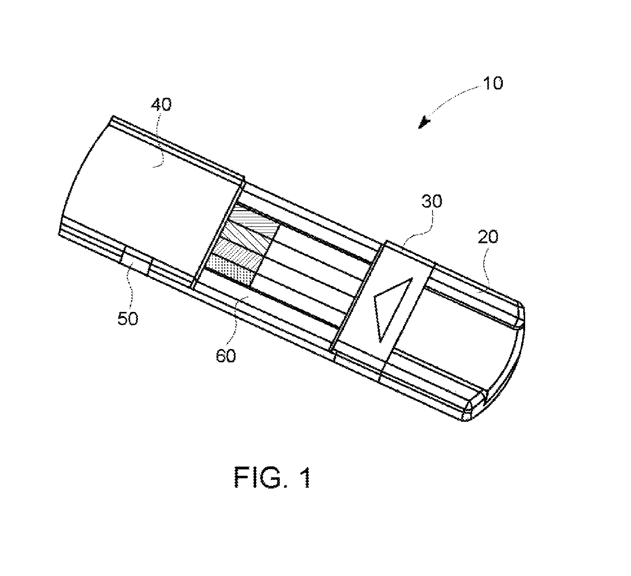
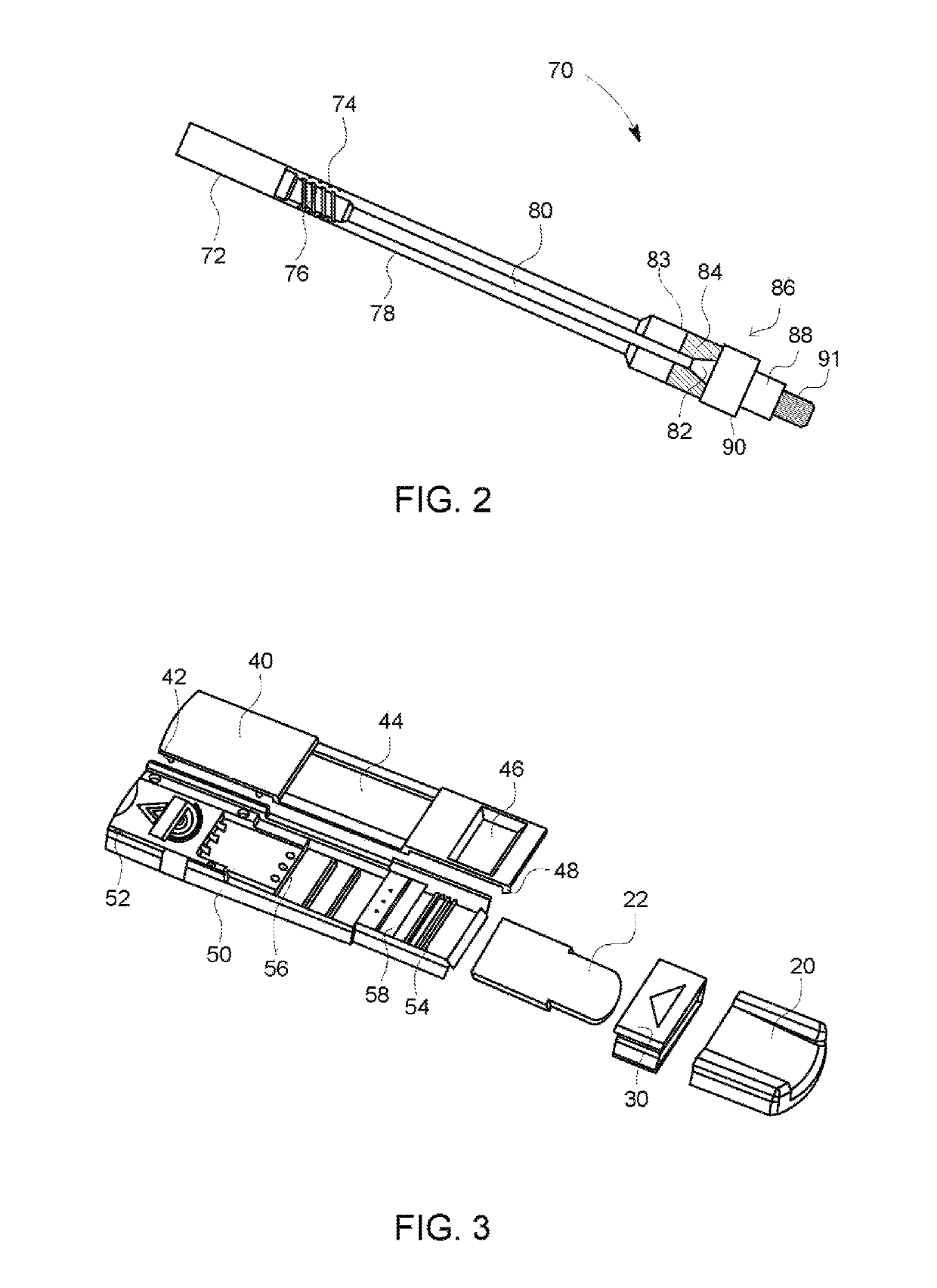
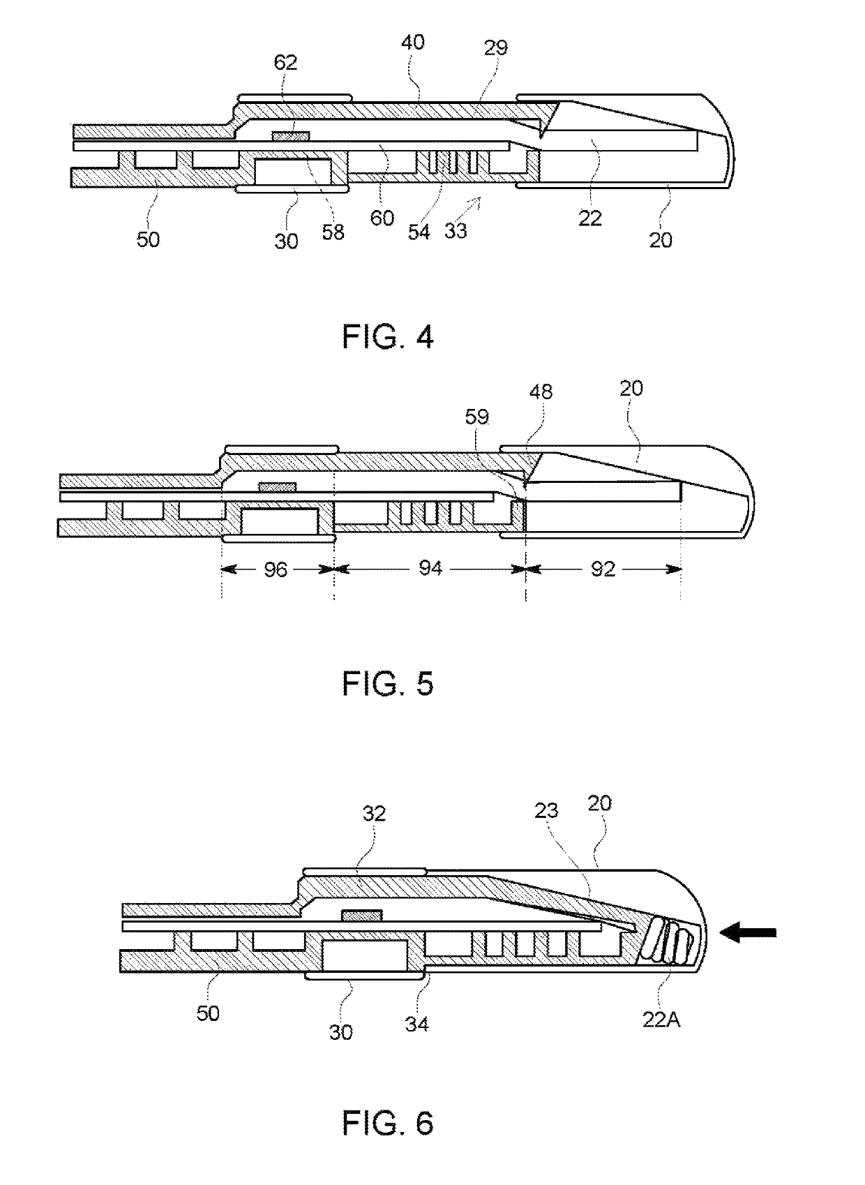
The present invention provides a device for testing liquid samples for the concentration of at least one analyte. The device includes a test cartridge with a flexible pad positioned over a portion of the test strip, a top component fitting onto the base component, and a cap slidable over the test cartridge. The cap includes an internal ramp causing the top component to be pressed towards the base component when the cap is slid onto the test cartridge. The device also includes auxiliary supports for supporting at least a portion of the test strip, and a sample releasing region for receiving a sample. The sample releasing region includes a sample releasing fluid for removing the sample from the swab. The device can be used with a separate applicator for collecting samples. The technical effects of the invention include improved accuracy and efficiency in testing liquid samples for the concentration of analytes.

Problems solved by technology

Unfortunately, although they can be fast, inexpensive, and simple-to-use, depending on the type of condition being detected, these tests provide a typical accuracy of between 75% and 95%, falling short of the 99% or above accuracy generally considered to be necessary for a confirmatory test, and providing no objective measure of a quantitative result, i.e. the concentration of a given drug present in the liquid being tested.
The reasons for the insufficient accuracy in many rapid in vitro diagnostic (IVD) test devices are primarily due to their current lack of overall higher sensitivity and specificity.
These attempts have met with limited success in some types of testing, but do not provide the desired accuracy in many others.
Also, pretreatment with two or more of the above pretreatments exacerbates the difficulties in obtaining uniform manufacturing due to potential incompatibilities between the pretreatment chemicals.
For example, the pH conditioner might disrupt the effectiveness of the non-specific blocking member molecules.
Further, lot-to-lot variation in the manufacture of many IVD test devices can often lead to ambiguous results, such as false negatives as well as weak false positives, so-called “ghost lines” or “phantom lines”.
In this way, if a non-analyte molecule or clump of molecules blocks access between analytes and binding members for only a few seconds, it may be enough to induce a false negative result.
Further, clumps of non-analyte molecules can carry an overabundance of the labeled mobilizable binding members to the second affinity binding site to generate a false positive result.
However, prior lateral flow devices suffer from low accuracy as detailed above.
Current lateral flow strips cannot provide the necessary sensitivity and specificity within the time normally allotted to a typical law enforcement action such as a traffic stop.
The low accuracy can be due to a number of problems unique to lateral flow-type tests.
First, there is often uneven movement of the immunoparticles within the nitrocellulose membrane.

Method used


Image

  • Rapid diagnostic test device and sampling method using driven flow technology
  • Rapid diagnostic test device and sampling method using driven flow technology
  • Rapid diagnostic test device and sampling method using driven flow technology

Examples


Embodiment Construction

[0038]The terminology used herein is for the purpose of describing particular embodiments only and is not intended to be limiting of the invention. As used herein, the term “and / or” includes any and all combinations of one or more of the associated listed items. As used herein, the singular forms “a,”“an,” and “the” are intended to include the plural forms as well as the singular forms, unless the context clearly indicates otherwise. It will be further understood that the terms “comprises” and / or “comprising,” when used in this specification, specify the presence of stated features, steps, operations, elements, and / or components, but do not preclude the presence or addition of one or more other features, steps, operations, elements, components, and / or groups thereof.

[0039]Unless otherwise defined, all terms (including technical and scientific terms) used herein have the same meaning as commonly understood by one having ordinary skill in the art to which this invention belongs. It wi...


PUM

PropertyMeasurementUnit
concentrationaaaaaaaaaa
flexibleaaaaaaaaaa
molecular affinityaaaaaaaaaa

Abstract

A progressive compression driven flow cartridge for analyzing liquids is coupled with convenient sampling methods for different applications. A one-step device provides for direct sample collection upon a sample pad annexed to the cartridge. The sample pad can deliver sample to the test strips, while saving a portion of the sample pad for further laboratory confirmation use. If the sample collecting pad is not suitable to collect the sample, such as the case of biological substances inside the human body, such as within the nose or throat, a two-step device can include a long-arm swab applicator and a specialized chamber in which some amount of liquid can dissolve biological substances as specimen. The specimen can then be transferred onto the cartridge, either by application to the sample pad, or into the device through a sample window. Each method provides a qualitative analysis much faster than traditional rapid diagnostic devices.

Description

BACKGROUND OF THE INVENTION1. Field of the Invention[0001]One or more embodiments of the invention relate generally to apparatus for analyzing liquids, such as body fluids, using labeled molecular affinity binding, such as immunochromatography. More particularly, the invention relates to a progressive compression driven flow cartridge for analyzing liquids, such as some bodily fluids and tracing biological substances, coupled with convenient sampling methods in different applications.2. Description of Prior Art and Related Information[0002]The following background information may present examples of specific aspects of the prior art (e.g., without limitation, approaches, facts, or common wisdom) that, while expected to be helpful to further educate the reader as to additional aspects of the prior art, is not to be construed as limiting the present invention, or any embodiments thereof, to anything stated or implied therein or inferred thereupon.[0003]Labeled molecular affinity bindi...

Claims


Application Information

Patent Timeline
Patent Type & Authority Patents(United States)
IPC IPC(8): G01N33/53G01N1/02G01N33/543
CPCG01N33/5302G01N1/02G01N33/54386G01N2001/028B01L3/5023B01L2300/046B01L2300/0825B01L2400/0406B01L2300/123B01L2300/069B01L2300/045G01N33/54388
Inventor WANG, NAISHUCHANG CHIEN, MICHAEL
Owner DNT SCI RES
Learn More