Shower door

a shower door and door frame technology, applied in the field of shower doors, can solve the problems of affecting the inertia is also comparatively great, and the movable door is affected by the frame, so as to ensure the sliding speed the stability of the movable door

Active Publication Date: 2019-10-29
IDEAL SANITARY WARE CO LTD
View PDF17 Cites 8 Cited by
  • Summary
  • Abstract
  • Description
  • Claims
  • Application Information

AI Technical Summary

Benefits of technology

[0017]Since the closer is provided on the track of the shower door provided by the present invention and the clamping mouth is provided on the clamping member on the closer, when the movable door slides to a limit position, the limiting block of the limiting member slides to a position inside the clamping mouth, thus the sliding speed of the movable door is reduced, the movable door can be effectively prevented from causing a very great impact force to the frame and the track through the cushioning effect of the clamping member and the limiting member, and thus the movable door and the track are prevented from being damaged. In addition, since the limiting member is further provided with the anti-bouncing block and the anti-bouncing block is located below the track, the movable door can be prevented from falling off from the track through the joint effect of the limiting block located above the track and the anti-bouncing block located below the track.
[0018]Besides, since the limiting block and the anti-bouncing block are respectively located at the two ends of the limiting member body, when the movable door slides, the anti-bouncing block can better prevent the movable door from bouncing upwards, and thus the stable sliding of the movable door is guaranteed. In addition, since the limiting member is fixed on the movable door through two screws, the limiting member is prevented from rotating relative to the movable door and the relative position relationship among the limiting block, the anti-bouncing block and the track is guaranteed as well.
[0019]Further, since the clamping member can slide back and forth on the sliding groove of the closer, the clamping member slides with the limiting member in a process that the movable door slides back and forth, the limiting member slides to a position inside the clamping mouth of the clamping member after the movable door slides to a certain position, the sliding speed of the movable door is decreased when the limiting member slides into the clamping mouth, the movable door further needs to drive the clamping member to slide in the body of the closer after the limiting member slides into the clamping mouth, thus the sliding speed of the movable door is slowed down and thus the impact caused by the movable door to the frame is effectively decreased.
[0020]Besides, since one end of the sliding groove is provided with the concave hole, the clamping member is obliquely arranged when the clamping member slides to the end portion of the sliding groove, thus the limiting block is facilitated to slide into the clamping mouth of the clamping member and the limiting block is also facilitated to slide out of the clamping mouth when the movable door slides towards an opening direction.

Problems solved by technology

Since the weight of the movable door is comparatively great, when the movable door is opened and closed, usually a comparatively great force is needed for pushing.
However, since the weight of the movable door is great, the inertia is also comparatively great.
When the movable door is opened or closed to a limit position, the movable door will hit against the frame or a limiting member, and consequently a very great impact is caused to the movable door, the frame and the track.

Method used


Image

  • Shower door
  • Shower door
  • Shower door

Examples


Embodiment Construction

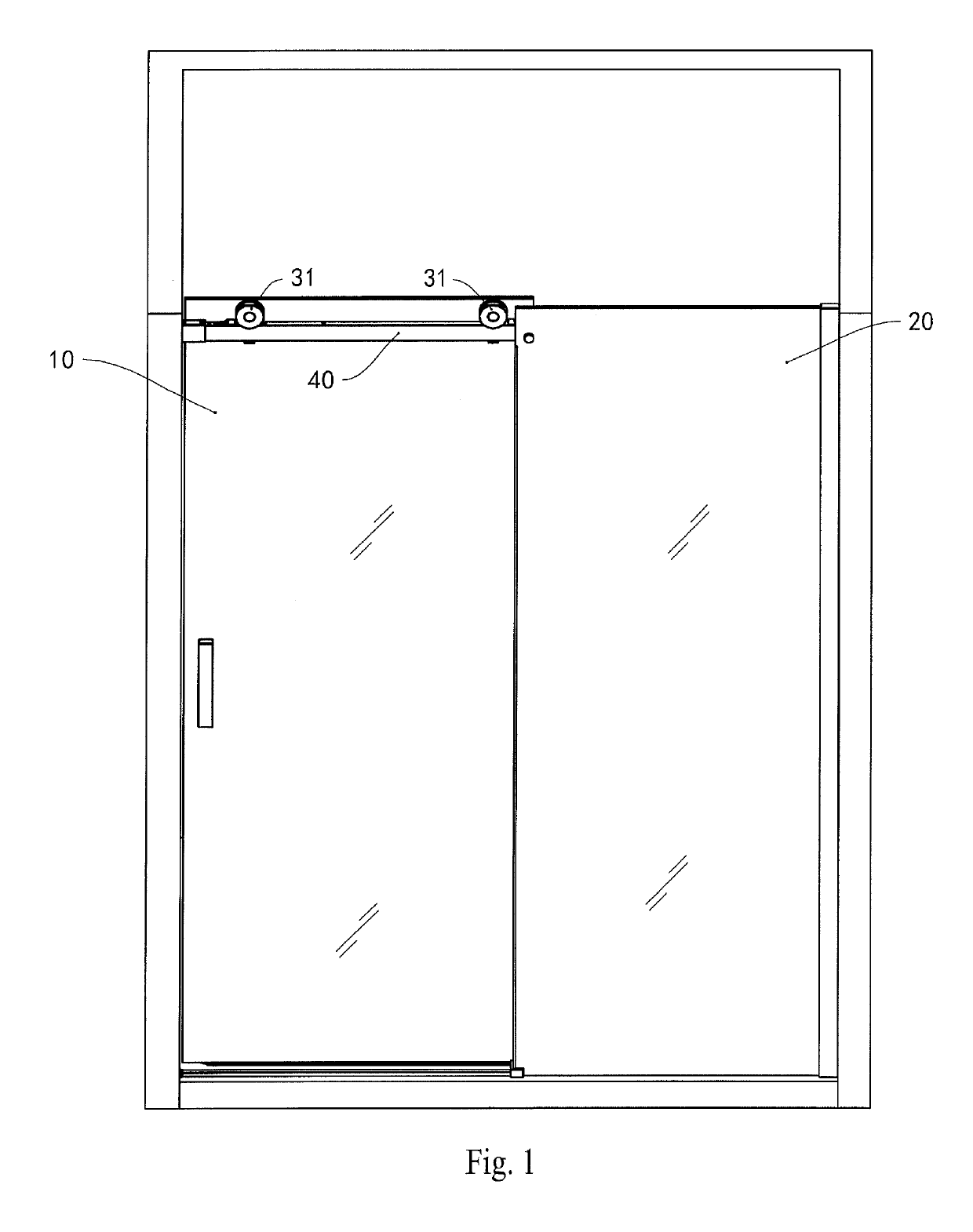
[0033]A shower door provided by the present invention is installed in a shower room. Referring to FIG. 1, the shower door provided by this embodiment comprises a movable door 10 and a fixed door 20, a track assembly 40 is provided at upper ends of the movable door 10 and the fixed door 20, and the movable door 10 and the fixed door 20 are respectively arranged on two sides of the track assembly 40. As illustrated in FIG. 1, the movable door 10 is located on one side, close to a paper surface, of the track assembly 40, and the fixed door 20 is located on one side, away from the paper surface, of the track assembly 40. In addition, the movable door 10 and the fixed door 20 are arranged in parallel, the fixed door 20 is fixed relative to the track assembly 40 and the movable door 10 can slide back and forth relative to the track assembly 40.

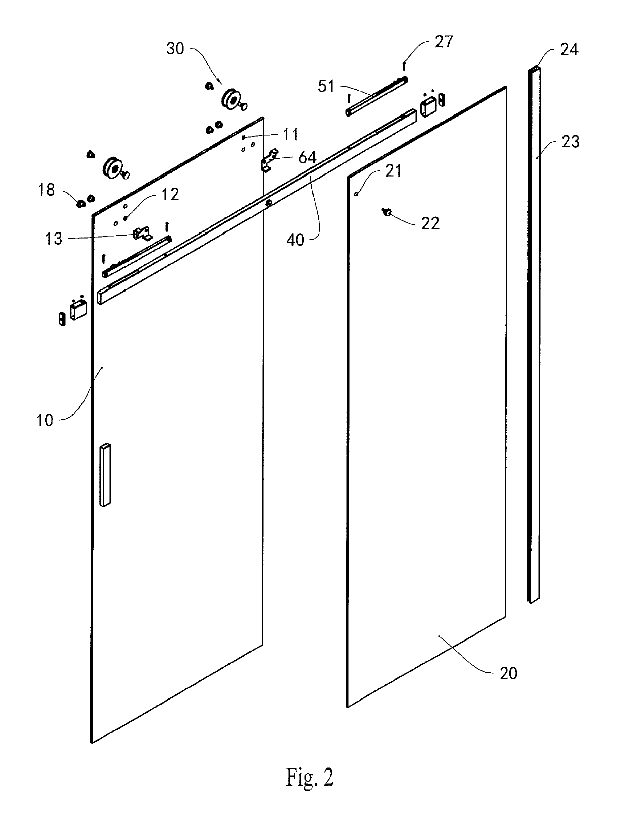
[0034]Referring to FIG. 2, the upper end of the movable door 10 is provided with two through holes 11 and the two through holes 11 are respectively...


PUM


Abstract

A shower door comprises a movable door, wherein at least one rolling wheel is fixed on the movable door, and at least one limiting member is fixed on the movable door; the shower door further comprises a track, the track is arranged below the rolling wheel, a closer is fixed on the track, the closer comprises a clamping member and a middle portion of the clamping member is provided with a clamping mouth facing upwards; and the limiting member comprises a limiting block and an anti-bouncing block, wherein the limiting block is located above the track, the limiting block is capable of being clamped in the clamping mouth of the clamping member and the anti-bouncing block is located below the track.

Description

CROSS REFERENCE TO RELATED APPLICATIONS[0001]The present application is a national phase entry under 35 U.S.C. § 371 of International Application No. PCT / CN2016 / 084513, filed Jun. 2, 2016, which claims priority from Chinese Patent Application No. 201610330855.X filed May 18, 2016, all of which are hereby incorporated herein by reference.TECHNICAL FIELD[0002]The present invention relates to the field of bathroom accessories, in particular to a shower door mounted in a shower room. The present invention is based on a Chinese invention patent application No. CN201610330855.X filed on May 18, 2016, which is incorporated herein by reference in its entirety.BACKGROUND ART[0003]Nowadays, people usually arrange a shower room in a toilet during decoration. Existing shower rooms usually use shower doors with glass plates. Existing shower doors are mainly divided into two structures, respectively including openable and closable doors with tracks and hinge doors with hinges.[0004]A hinge door h...

Claims


Application Information

Patent Timeline
Patent Type & Authority Patents(United States)
IPC IPC(8): A47K3/34E05F5/00E05D13/00E05D15/06E06B3/46
CPCE05F5/003A47K3/34E05D15/0652E05D15/063E06B3/4636E05D13/00E05Y2201/212E05Y2900/112E05Y2201/224E05Y2201/614E05Y2900/114E05D15/10A47K3/286
Inventor WEI, WUXIANG
Owner IDEAL SANITARY WARE CO LTD
Why Eureka
Try Eureka