Tire cure mold and method of manufacturing tire

a technology of molds and tires, applied in the field of molds, can solve the problems of unavoidable degradation of appearance quality and tire appearance quality, and achieve the effects of improving the appearance quality, preventing defective formation of groove bottom projection, and improving tire appearance quality

Inactive Publication Date: 2019-10-29
TOYO TIRE & RUBBER CO LTD
View PDF6 Cites 4 Cited by
  • Summary
  • Abstract
  • Description
  • Claims
  • Application Information

AI Technical Summary

Benefits of technology

[0006]The present invention has been made with the above-described circumstances in view and its object is to provide a tire cure mold capable of improving appearance quality of a tire by preventing defective formation of groove bottom projections and a method of manufacturing the tire by use of the tire cure mold.
[0008]Because the tire cure mold has the second vent hole open in the bottom face of the depression for forming the groove bottom projection in addition to the first vent hole open in the tread molding face, it is possible to reduce air remaining in the depression during the cure. Moreover, because the spring vent is mounted in the second vent hole, it is possible to suppress formation of a spew on the groove bottom projection. As a result, it is possible to prevent defective formation of the groove bottom projection to thereby improve appearance quality of the tire.
[0010]It is preferable that a spring vent is mounted in the first vent hole and an outer diameter of the spring vent mounted in the second vent hole is smaller than an outer diameter of the spring vent mounted in the first vent hole. In this case, a mark which the spring vent leaves on the groove bottom projection is less conspicuous, which effectively improves the appearance quality.
[0011]The present invention provides a method of manufacturing a tire comprising a step of performing cure by setting an uncured tire in a cavity of the tire cure mold mentioned above and heating and pressurizing the uncured tire. With this method, it is possible to prevent defective formation of the groove bottom projection as described above to thereby improve the appearance quality of the tire.

Problems solved by technology

If air remains in the depressions in the cure, incomplete flow of rubber causes defective formation of the groove bottom projections, which may degrade appearance quality of the tire in some cases.
Even if the vent holes are formed in the depressions, rubber protrusions (also called “spews”) are formed due to entrance of the rubber into the vent holes and therefore degradation of the appearance quality is unavoidable.

Method used


Image

  • Tire cure mold and method of manufacturing tire
  • Tire cure mold and method of manufacturing tire
  • Tire cure mold and method of manufacturing tire

Examples


Embodiment Construction

[0016]An embodiment of the present invention will be explained with reference to the drawings.

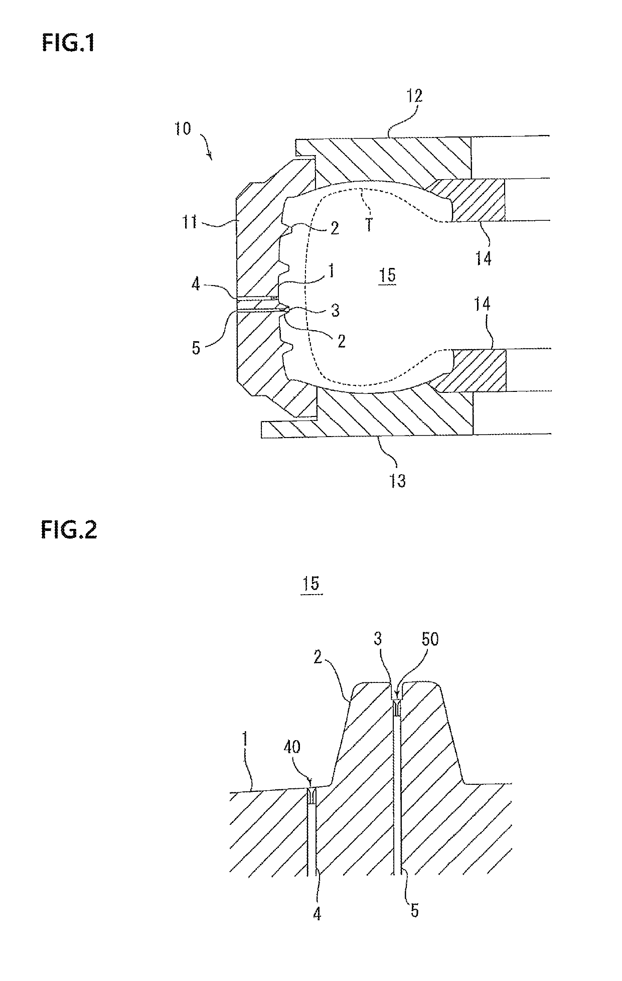
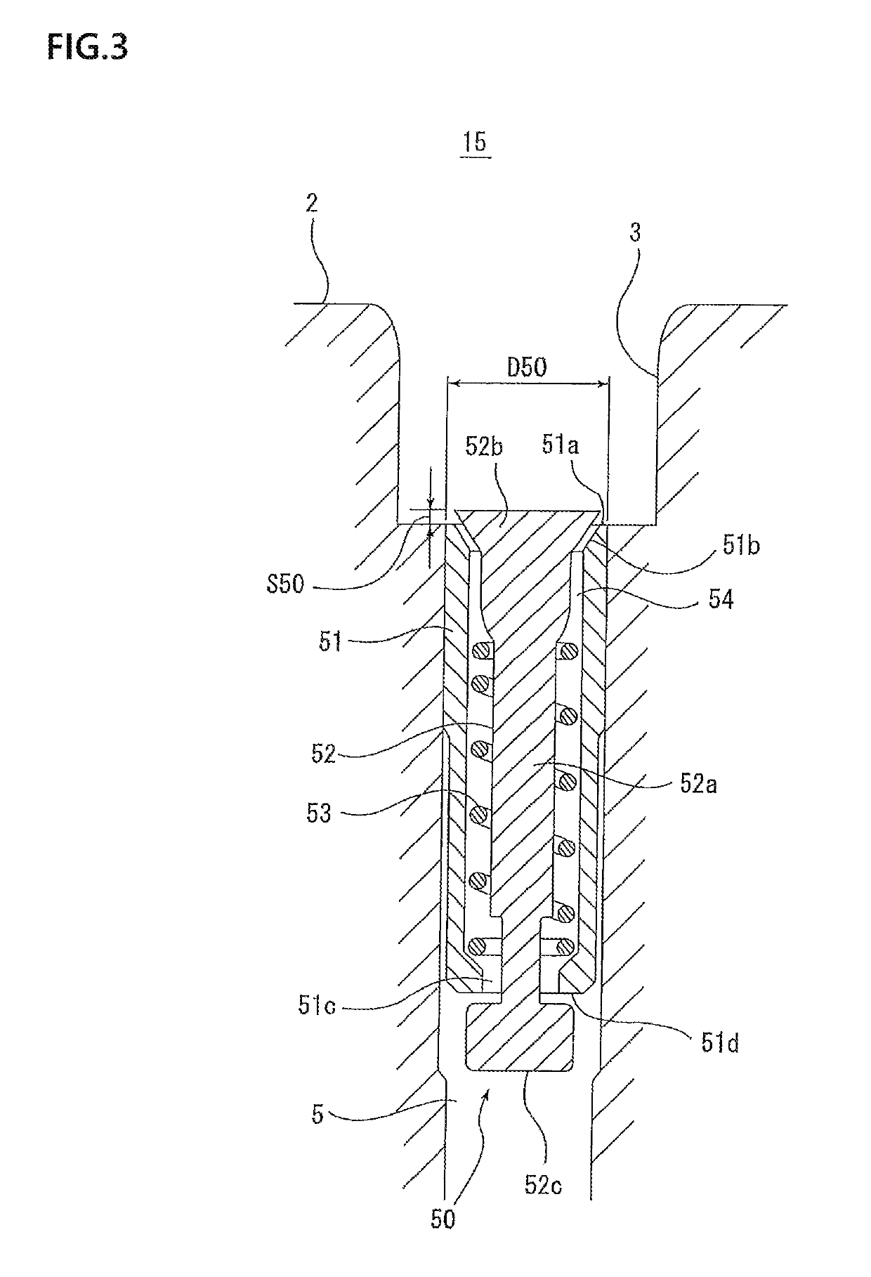
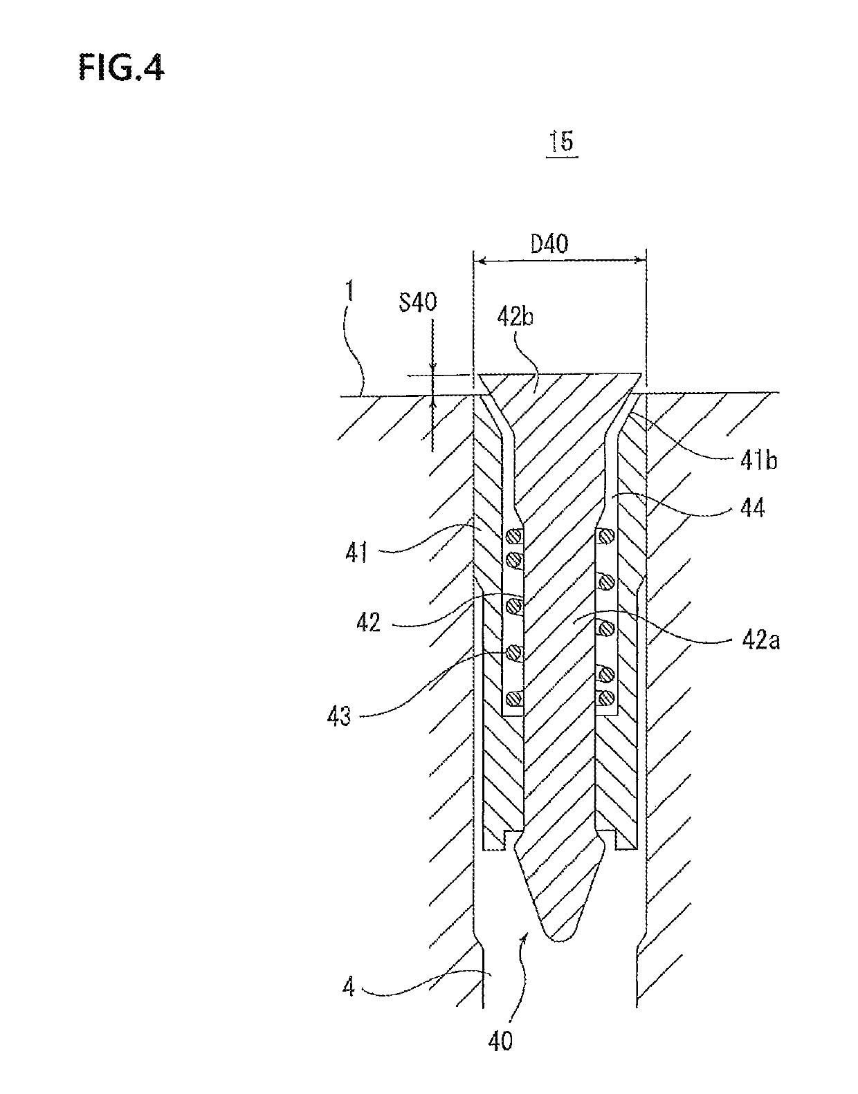
[0017]FIG. 1 shows a section of a tire cure mold 10 along a tire meridian and the tire cure mold 10 is in a clamped state. A tire T is set with a tire width direction oriented in a vertical direction. In FIG. 1, a left side corresponds to an outer side in a tire diametrical direction and a right side corresponds to an inner side in the tire diametrical direction. FIG. 2 is an enlarged view of a relevant part of FIG. 1 and FIGS. 3 and 4 are further enlarged views of relevant parts of FIG. 2. In each of FIGS. 2 to 4, a lower side corresponds to the outer side in the tire diametrical direction and an upper side corresponds to the inner side in the tire diametrical direction.

[0018]As shown in FIGS. 1 and 2, the tire cure mold 10 includes a tread molding face 1 which comes in contact with a tread face of the tire T set in a cavity 15, protruding portions 2 for forming groove portions and protrud...


PUM

PropertyMeasurementUnit
outer diameteraaaaaaaaaa
outer diametersaaaaaaaaaa
outer diameteraaaaaaaaaa

Abstract

A tire cure mold has a tread molding face that comes in contact with a tread face of a tire set in a cavity, a protruding portion for forming a groove portion and protruding inward in a tire diametrical direction from the tread molding face, a depression for forming a groove bottom projection and formed by recessing a top face of the protruding portion, a first vent hole open in the tread molding face, a second vent hole open in a bottom face of the depression, and a spring vent mounted in the second vent hole.

Description

BACKGROUND OF THE INVENTIONField of the Invention[0001]The present invention relates to a tire cure mold used for cure of a tire and a method of manufacturing the tire.Description of the Related Art[0002]A tire cure mold has a tread molding face which comes in contact with a tread face of a tire. The tread molding face is provided with a recessed and protruding shape for forming a tread pattern. The recessed and protruding shape is formed by protruding portions for forming groove portions and protruding inward in a tire diametrical direction from the tread molding face and recessed portions for forming land portions and divided by the protruding portions. The tread molding face is provided with a plurality of vent holes for exhausting excess air between the tread face of the tire and the tread molding face to an outside and the vent holes are arranged on bottom faces of the recessed portions.[0003]In some cases, the groove portions in the tread face of the tire may be provided with ...

Claims


Application Information

Patent Timeline
Patent Type & Authority Patents(United States)
IPC IPC(8): B29D30/06B29C33/10B29D30/08B29C37/00B60C11/13B29L30/00
CPCB29C37/0053B29C33/10B29D30/08B29L2030/002B29D30/0606B29D2030/0617B29D2030/0612B60C2011/1361
Inventor ANDO, TAKAHIRO
Owner TOYO TIRE & RUBBER CO LTD
Why Eureka
Try Eureka