Liquid container

a liquid container and container technology, applied in the field of liquid containers, can solve the problems of printing failure, and reducing the possibility of air bubble mixing

Active Publication Date: 2019-10-29
SEIKO EPSON CORP
View PDF25 Cites 0 Cited by
  • Summary
  • Abstract
  • Description
  • Claims
  • Application Information

AI Technical Summary

Benefits of technology

[0005](1) According to a first aspect of the present disclosure, there is provided a liquid container configured to be mounted to a carriage that reciprocates in an X direction. The liquid container comprises an upper wall and a bottom wall opposed to each other in a Z direction that intersects with the X direction; a first side wall and a second side wall opposed to each other in a Y direction that intersects with the X direction and the Z direction; a third side wall and a fourth side wall opposed to each other in the X direction; a liquid supply port provided in the bottom wall; a first chamber provided on a +Z direction side that is an upper wall side in the Z direction; a second chamber provided on a −Z direction side that is a bottom wall side in the Z direction; a partition wall configured to part the first chamber from the second chamber; and a connecting hole configured to connect the first chamber with the second chamber. The second chamber is connected with the liquid supply port. The first chamber is connected with the liquid supply port via the connecting hole and the second chamber. The second chamber includes a return flow path that is turned back along the X direction. A liquid contained in the first chamber is flowed from the connecting hole through the return flow path to the liquid supply port. In the liquid container of this aspect, the return flow path turned back along a moving direction of the liquid container is provided in the second chamber. This configuration reduces the possibility that air bubbles are mixed in the liquid supplied from the liquid container.
[0006](2) In the liquid container of the above aspect, the return flow path may include a first flow path in which the liquid flows from the third side wall toward the fourth side wall, and a second flow path in which the liquid flows from the fourth side wall toward the third side wall. The liquid container of this configuration increases the flow path length of the return flow path.
[0007](3) In the liquid container of the above aspect, the first chamber may be provided with an air introducing hole configured to introduce the air from outside of the first chamber into the first chamber. The liquid container of this configuration provides the good pressure state in the first chamber.

Problems solved by technology

The inflow of air bubbles to the print head in the printer is likely to cause a printing failure.
This problem is not characteristic of the liquid container configured to introduce the air into the liquid container but may arise when a certain amount of the air is present in the liquid container.
This problem is commonly found in liquid containers configured to contain liquids other than ink and liquid ejection apparatuses using such liquid containers.
This configuration reduces the possibility that air bubbles are mixed in the liquid supplied from the liquid container.
(9) In the liquid container of the above aspect, the connecting hole may have such dimensions and shape that do not allow for gas-liquid exchange between the first chamber and the second chamber.
This configuration reduces the possibility that air bubbles are mixed in the liquid supplied from the liquid container.

Method used


Image

  • Liquid container
  • Liquid container
  • Liquid container

Examples


first embodiment

A. First Embodiment

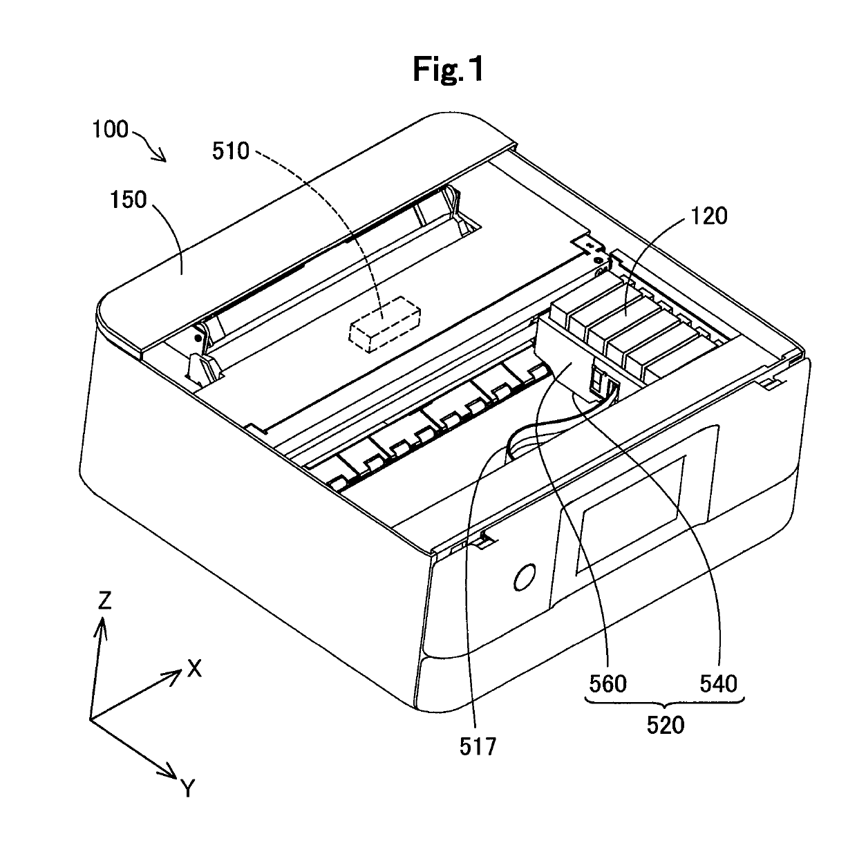
[0058]FIG. 1 is a perspective view illustrating the schematic configuration of a liquid supply system 100 according to a first embodiment. X, Y and Z axes that are orthogonal to one another are illustrated in FIG. 1. The X, Y and Z axes of FIG. 1 correspond to X, Y and Z axes of the other drawings. The liquid supply system 100 includes cartridges 120 as liquid containers and a printer 150 as a liquid ejection apparatus. In the liquid supply system 100, the cartridges 120 are mountable to a carriage 520 of the printer 150 by the user. According to this embodiment, “liquid” denotes ink.

[0059]The cartridge 120 of the liquid supply system 100 is configured to contain ink as a printing material (liquid) inside thereof. The ink contained in the cartridge 120 is supplied to a liquid ejection head 540 via a liquid supply port and a liquid introducing portion described later. According to this embodiment, a plurality of the cartridges 120 are detachably mounted to a holder...

second embodiment

B. Second Embodiment

[0102]FIG. 19 is an exploded perspective view illustrating a cartridge 120A according to a second embodiment. FIG. 20 is a front view illustrating a main body member 301 according to the second embodiment. The cartridge 120A of the second embodiment differs from the cartridge 120 of the first embodiment by the configuration of a second chamber 320 in the main body member 301 but otherwise has a similar configuration to that of the cartridge 120 of the first embodiment. In the respective embodiments described below, members that have like functions to those of the first embodiment are expressed by the like reference signs to those of the first embodiment.

[0103]Like the first embodiment, the second chamber 320 of the second embodiment includes a return flow path 321 that is turned back along the X direction. According to this embodiment, the return flow path 321 includes a first flow path 323 in which ink flows from the third wall portion 203-side toward the fourth...

third embodiment

D. Third Embodiment

[0112]FIG. 21 is an exploded perspective view illustrating a cartridge 120B according to a third embodiment. FIG. 22 is a front view illustrating a main body member 301 according to the third embodiment. FIG. 23 is a perspective view illustrating the main body member 301 according to the third embodiment. FIG. 24 is a perspective view illustrating the periphery of a second chamber 320. FIG. 25 is a diagram illustrating a second flow path 324 viewed from the +Z direction side. FIG. 26 is a sectional view taken along XXVI-XXVI in FIG. 25.

[0113]A thick one-dot chain line arrow indicates the flow route of ink in FIG. 22. A first chamber 310 is formed on the +Z direction side of a partition wall 330 in the main body member 301. The first chamber 310 is a space of an approximately rectangular sectional shape surrounded by an inner surface of the second wall portion 202, an inner surface of the third wall portion 203, an inner surface of the fourth wall portion 204, an i...


PUM


Abstract

There is provided a liquid container that comprises an upper wall and a bottom wall; a liquid supply port provided in the bottom wall; a first chamber provided on a +Z direction side that is an upper wall side; a second chamber provided on a −Z direction side that is a bottom wall side; a partition wall configured to part the first chamber from the second chamber; and a connecting hole configured to connect the first chamber with the second chamber. The second chamber is connected with the liquid supply port. The first chamber is connected with the liquid supply port via the connecting hole and the second chamber. The second chamber includes a return flow path that is turned back along an X direction. A liquid contained in the first chamber is flowed from the connecting hole through the return flow path to the liquid supply port.

Description

CROSS-REFERENCE TO RELATED APPLICATION[0001]The present application claims priority from Japanese patent application 2017-010857 filed on Jan. 25, 2017 and Japanese patent application 2017-106444 filed on May 30, 2017, the entireties of the contents of which are hereby incorporated by reference into this application.BACKGROUNDField[0002]The disclosure relates to a liquid container configured to contain a liquid such as ink.Related Art[0003]JP 2014-40080A, JP 1106-40041A and JP 3807115B disclose various printers configured to introduce the air into a liquid container. The printers disclosed in JP 2014-40080A and JP 1106-40041A are “on-carriage type” printers in which a liquid container is mounted on a holder of a carriage that moves a print head. The printer described in JP 3807115B is an “off-carriage type” printer in which a liquid container is not mounted on a carriage but is placed at a stationary position.[0004]In these various printers, air bubbles are likely to be mixed in ink...

Claims


Application Information

Patent Timeline
Patent Type & Authority Patents(United States)
IPC IPC(8): B41J2/21B41J2/175B41J2/19
CPCB41J2/211B41J2/19B41J2/17523B41J2/17513B41J2/17553B41J2002/17516B41J2/17563
Inventor KOBAYASHI, ATSUSHITOBA, KOICHIYOSHIKAWA, YASUHIKOTANAKA, RYOICHIMIZUTANI, TADAHIRO
Owner SEIKO EPSON CORP
Why Eureka
Try Eureka