Vehicle front portion structure

a front portion and vehicle technology, applied in the direction of superstructure connections, superstructure subunits, vehicle components, etc., can solve the problems of excessive deformation of the inability to efficiently transfer the load to the inclined portion and the rear portion from the front portion of the front side member,

Active Publication Date: 2019-10-29
TOYOTA JIDOSHA KK
View PDF12 Cites 0 Cited by
  • Summary
  • Abstract
  • Description
  • Claims
  • Application Information

AI Technical Summary

Benefits of technology

[0006]According to the aspect, when a load from the front side of the vehicle acts on the front side member, the load is transferred to the front side member rear via the extending portion of the reinforcing member as well. Accordingly, the load from the front side of the vehicle can be transferred to the front side member rear more efficiently than in a case where the extending portion of the reinforcing member is not fixed to the front side member rear.
[0008]According to the aspect, the load from the front side of the vehicle is dispersed and transferred to the torque boxes as well as the front side member rear via the extending portion of the reinforcing member. The extending portion of the reinforcing member, the front side member rear, and the torque boxes are fixed to one another at the positions where the extending portion of the reinforcing member, the front side member rear, and the torque boxes overlap one another, and thus the load from the extending portion of the reinforcing member can be directly transferred to the torque boxes. Accordingly, the load from the front side of the vehicle can be efficiently transferred to the torque boxes as well.
[0010]According to the aspect, a ridgeline extending in the width direction of the vehicle is formed at the boundary between the peripheral wall portion and the front wall portion of the torque box (In the present specification, “in the width direction of the vehicle” also means “substantially in the width direction of the vehicle”). The part of the torque box that is in the vicinity of the ridgeline is higher in strength and less likely to be deformed than the flat plate-shaped part where no ridgeline is formed. According to the aspect, the extending portion of the reinforcing member is fixed to an upper wall portion of the torque box. Accordingly, even when the load from the front side of the vehicle acts on the front wall portion of the torque box from the extending portion of the reinforcing member, the load is efficiently taken at the part of the torque box in the vicinity of the ridgeline that is behind the front wall portion. Accordingly, deformation of the box-shaped parts of the torque box such as the peripheral wall portion and the bottom wall portion can be appropriately suppressed.
[0014]According to the aspect, the side surface portions of the reinforcing member are fixed to the side surfaces of the inner peripheral surface of the front side member, and thus collapse of the cross-sectional shape of the front side member during the action of the load on the front side member can be appropriately suppressed. Since the reinforcing member is provided with the extending portion as described above, the load can be appropriately transferred in the reinforcing member. In other words, according to the aspect, sectional collapse of the front side member can be appropriately suppressed and the load can be appropriately transferred to the front side member rear by the single reinforcing member.

Problems solved by technology

Accordingly, once a load from the front side of the vehicle acts on the front side member of the vehicle front portion structure disclosed in JP 2003-231483 A, the front side member is bent in both end portions of the inclined portion in the front-rear direction of the vehicle and the load may not be efficiently transferred to the inclined portion and the rear portion from the front portion of the front side member.
When the load cannot be appropriately transferred to the inclined portion and the rear portion of the front side member, the front portion of the front side member may undergo excessive deformation, which is not desirable.

Method used


Image

  • Vehicle front portion structure
  • Vehicle front portion structure
  • Vehicle front portion structure

Examples


Embodiment Construction

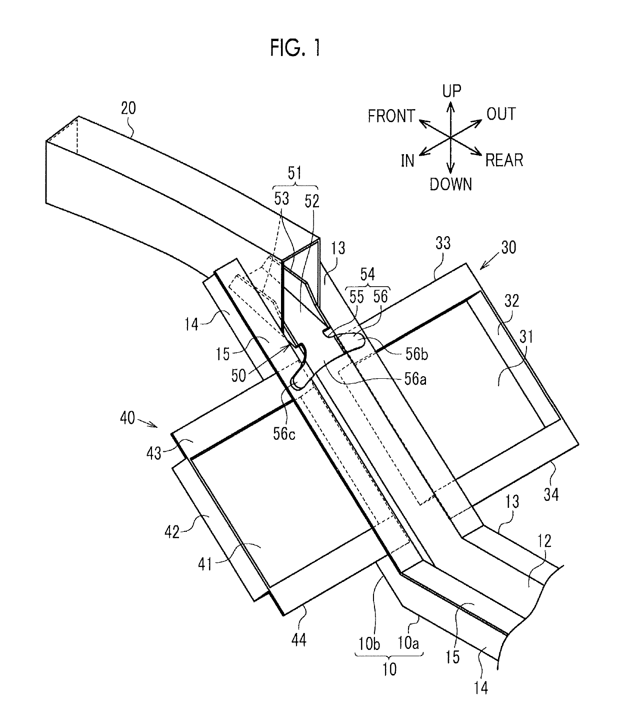
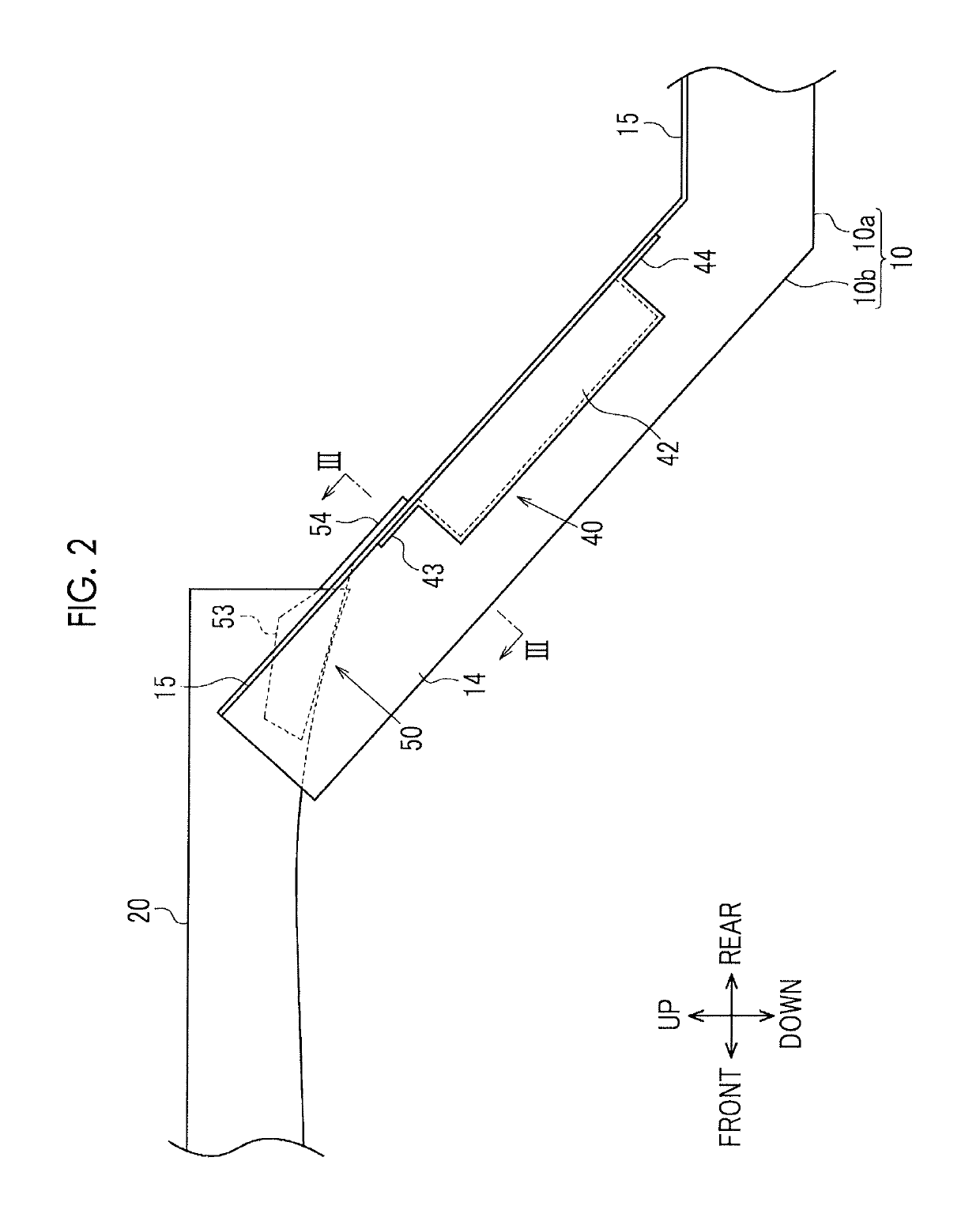
[0020]Hereinafter, an embodiment will be described with reference to FIGS. 1 to 4. In the following description, a vehicle front portion structure that is on the right side of a vehicle will be described as an example. As illustrated in FIGS. 1 and 2, a front side member rear 10 of the vehicle front portion structure (hereinafter, simply referred to as a member rear 10) extends in the front-rear direction of the vehicle as a whole. The member rear 10 is broadly divided into a linear portion 10a extending in the front-rear direction of the vehicle and an inclined portion 10b obliquely extending from the front end of the linear portion 10a to the upper front side of the vehicle. The rear end of the linear portion 10a of the member rear 10 is connected to the front end of a floor side member (not illustrated). A plate-shaped dash panel (not illustrated) and so on are disposed on the upper side of the inclined portion 10b.

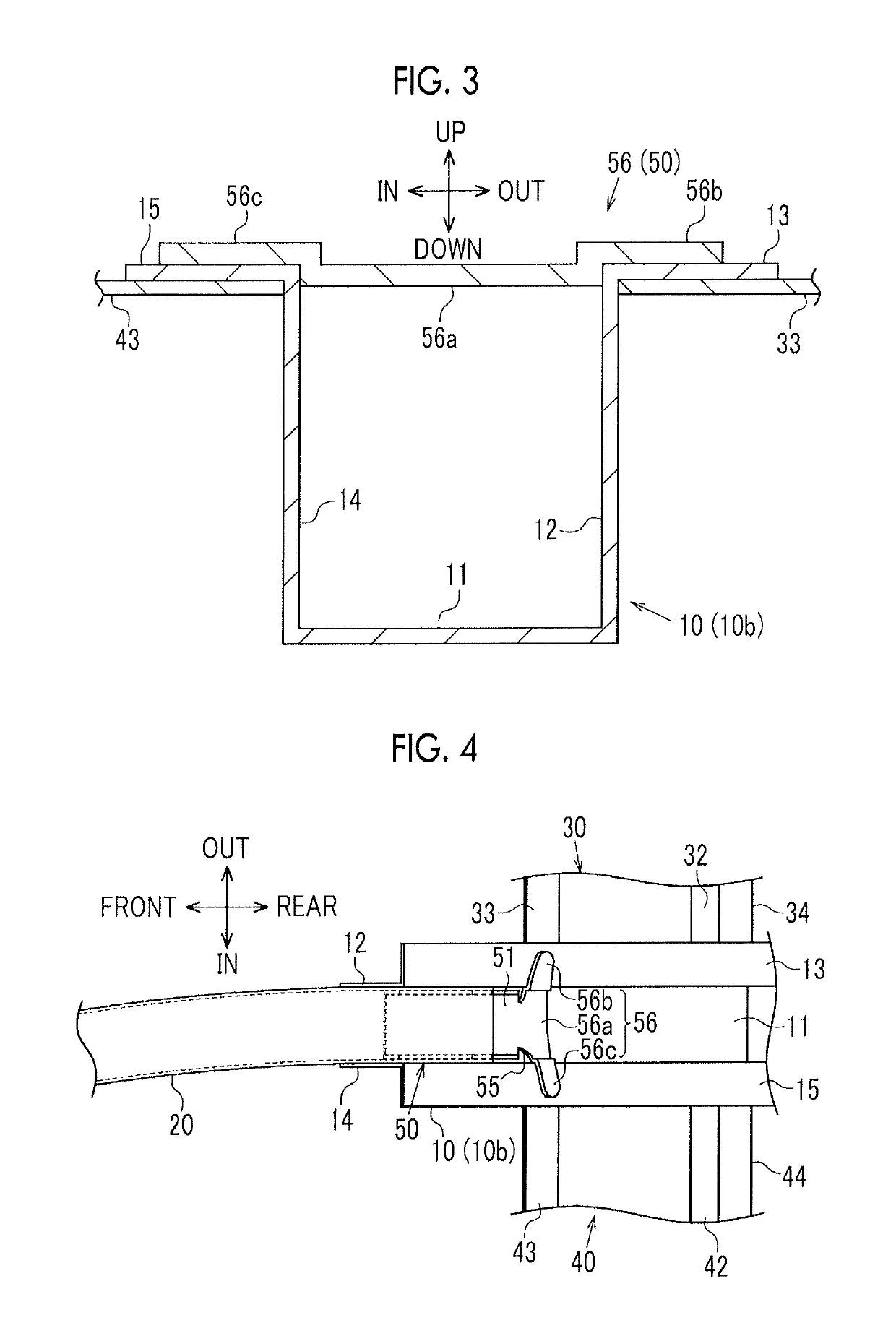
[0021]As illustrated in FIG. 3, the member rear 10 has a hat-sha...


PUM


Abstract

A vehicle front portion structure includes a front side member rear extending in a front-rear direction of a vehicle, a part of a front side of the front side member rear being an inclined portion inclined such that a position of the inclined portion rises toward a front side of the vehicle, and a tubular front side member fixed to the inclined portion of the front side member rear and extending from the inclined portion to the front side of the vehicle. A plate-shaped reinforcing member is fixed to an inner peripheral surface of the front side member, the reinforcing member is provided with an extending portion extending to a rear side of the vehicle behind a rear end of the front side member, and the extending portion is fixed to the front side member rear.

Description

INCORPORATION BY REFERENCE[0001]The disclosure of Japanese Patent Application No. 2016-251938 filed on Dec. 26, 2016 including the specification, drawings and abstract is incorporated herein by reference in its entirety.BACKGROUND1. Technical Field[0002]The present disclosure relates to a vehicle front portion structure.2. Description of Related Art[0003]Japanese Unexamined Patent Application Publication No. 2003-231483 (JP 2003-231483 A) discloses a vehicle front portion structure that is provided with a front side member which extends in the front-rear direction of a vehicle as a whole. The front side member is provided with a rear portion extending in the front-rear direction of the vehicle, an inclined portion obliquely extending toward the upper front side of the vehicle from the front end of the rear portion, and a front portion extending forward from the front end of the inclined portion.SUMMARY[0004]The inclined portion of the front side member of the vehicle front portion s...

Claims


Application Information

Patent Timeline
Patent Type & Authority Patents(United States)
IPC IPC(8): B62D21/02B62D25/08B62D27/02
CPCB62D25/08B62D27/02B62D21/02B62D25/2018
Inventor SHIMIZU, SATOSHI
Owner TOYOTA JIDOSHA KK
Why Eureka
Try Eureka