Biodegradable metallic vascular stent and application thereof

a vascular stent, biodegradable technology, applied in the field of biodegradable vascular stents, can solve the problems of limited use, thrombosis, long-term endothelial dysfunction, etc., and achieve the effects of improving mechanical properties, reducing maximum stress, and effective utilization of spa

Active Publication Date: 2019-11-05
SHANGHAI JIAOTONG UNIV
View PDF10 Cites 0 Cited by
  • Summary
  • Abstract
  • Description
  • Claims
  • Application Information

AI Technical Summary

Benefits of technology

[0007]An example embodiment of the present invention is a biodegradable metallic vascular stent, wherein the tubular base body with the structure element distinctive design provides a stent which allows minimize the maximum stress and plastic deformation in arched elements, with effective utilization of the space that is available for crimping. By means of improving the mechanical properties of biodegradable stent, including enough radial force and suitable corrosion rate, to meet the clinical requirements.
[0019]Compared with the prior art, the present innovation has the following beneficial effects:
[0020]1. In the present invention, the biodegradable stent, with good biocompatibility and uniform-degradation, allows for successful acute revascularization of coronary artery stenosis. The main advantage of the biodegradable stent is that following complete biodegradable, no foreign body remains in the vessel wall at long term follow-up, which may avoid the increased long-term risk of stent thrombosis seen with the permanent stent.
[0021]2. Compared to permanent stents, such as stainless steel, cobalt-based alloys and titanium-based alloys, biodegradable magnesium alloy stents or zinc alloy stent has inferior mechanical performance and show corrosion damage during their life when implanted. The conventional design for permanent stents are not suitable for biodegradable stent under large crimping and expanding deformation. One example aim of the patent is to provide a stent design for biodegradable material to overcome the problems described above. Due to the characteristic repeat units design that kink elements, bump elements, non-uniform radius arched elements and gradient width diagonal elements are introduced and adequate organized, a homogeneous distribution of stress and plastic deformation in the arched elements of the stent are accomplished. Therefore, the biodegradable stent according to the embodiment possess sufficient radial force, good bending flexibility, uniform deformation and residual stress distribution.
[0022]3. The approach according to some embodiment of the present invention is optimal morph the shape and rim of arched elements, diagonal elements and kink elements. The out contours of diagonal elements are parallel to the longitudinal axis after crimping, by means of matching the bending stiffness between arched elements and kink elements, in order to make full use of the space, ensure the sufficient crimp ability and avoid the self-contact. Therefore, the plastic deformation distribution of circumferential support structures are unify and the recoil of stent after crimping is reduced.
[0023]4. As the result of the shape optimization for the repeat unit, it has been discovered that the stent according to this invention embodiment has the optimal transmission of force from the central area of inner edge of arched elements to the whole area of arched elements and adjacent diagonal elements. Owing to the homogeneous distribution of plastic deformation, the stress concentration and the corrosion rate of stent after deployed are reduced and Corrosion fatigue behaved of stent is improved.

Problems solved by technology

However, permanent metallic implants have specific drawbacks which limit their more widespread use.
These limitations include long-term endothelial dysfunction, delayed re-endothelialization, thrombogenicity, permanent physical irritation, chronic inflammatory local reactions, and mismatches in mechanical behavior between stented and non-stented vessel areas, and importantly non-permissive or disadvantageous characteristics for later surgical revascularization.
After this period, the presence of stent within the body cannot provide any beneficial effects.
Other limitations seen in polymer stents include the inability to expand completely with balloon dilatation along with restenosis rates similar to those observed for conventional bare metal stents.
On another side, the corrosion of Fe-based alloys is generally too slow, as a result the implants would stay in human body for a too long time even after finishing their clinical role.
Due to the inferior elongation capability of Mg alloy under room temperature, the crown contour with high curvature in the stent described in above two patents will be damaged during crimping and expanding deformation.
The conventional uniform width struts cannot overcome the stress concentration factor, which will increase the stress corrosion rate in crucial part and decrease the corrosion fatigue life.

Method used


Image

  • Biodegradable metallic vascular stent and application thereof
  • Biodegradable metallic vascular stent and application thereof

Examples


embodiment 1

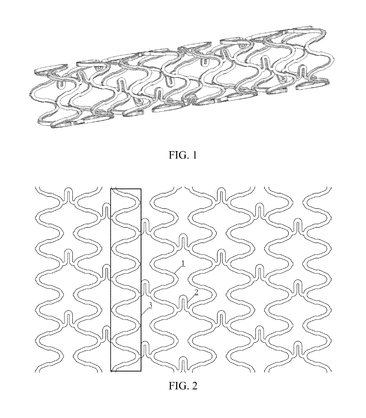
[0032]The present disclosure provides an example embodiment 1 of a biodegradable stent shown in FIG. 1, comprising a base body which is tubular with a lumen along a longitudinal axis, wherein the base body has a plurality of circumferential support structures 3 which are successively positioned along the longitudinal axis and are each composed of a sequence of repeat units 1; and each of the circumferential support structures has two or more connectors 2, wherein two adjacent circumferential support structures 3 are joined together by at least two of the connector 2, and each of the connectors 2 is attached to one of arched elements 12 of the two adjacent circumferential support structures 3 to be connected.

[0033]According to embodiment 1, the adjacent circumferential support structures 3 are specularly symmetric.

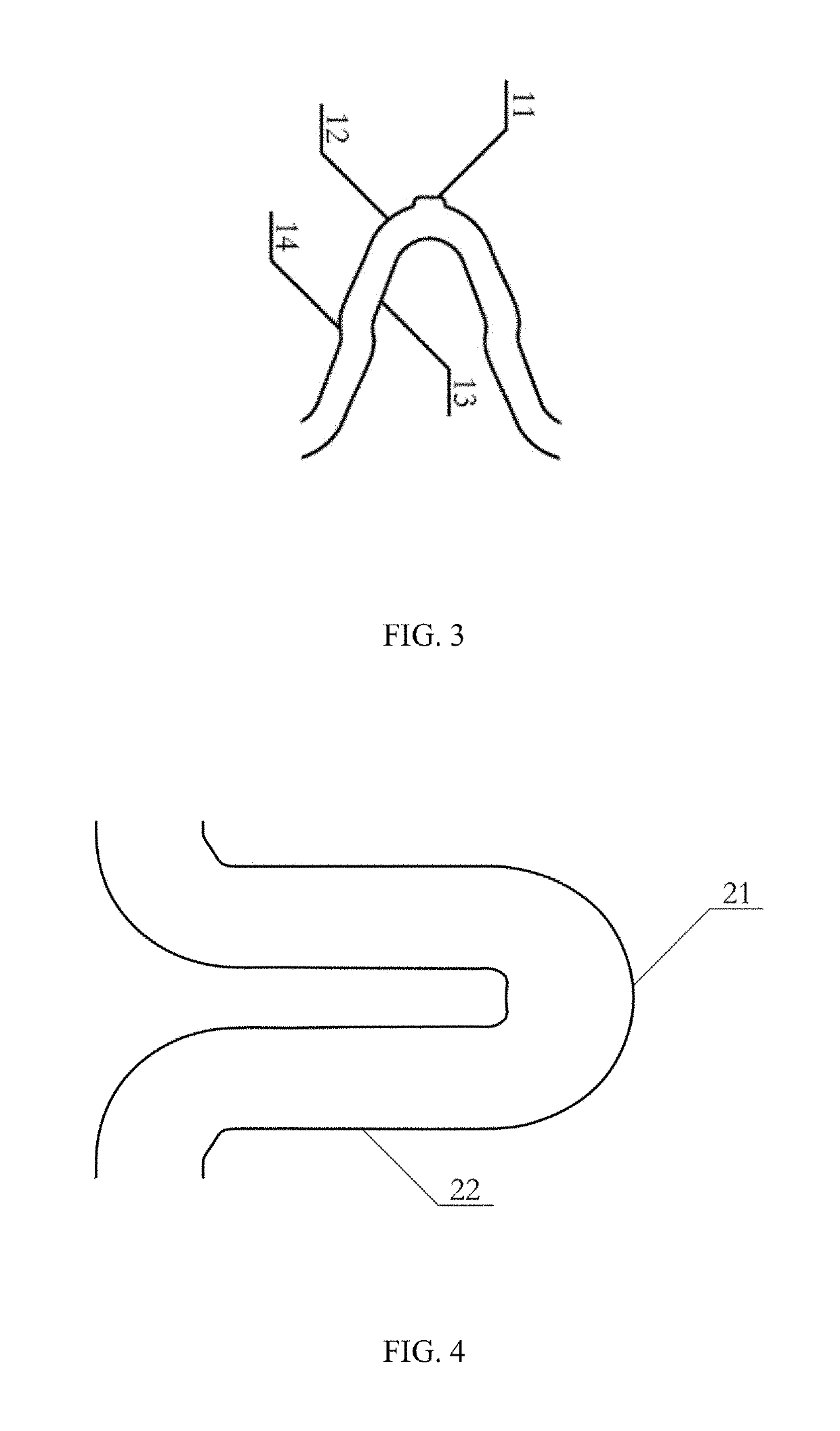
[0034]FIG. 4 shows the connectors 2, which are “n” shaped and comprise curved elements 21 and two straight elements 22; outer contours of curved element 21 are smooth curve...

embodiment 2

[0041]In an alternative embodiment 2 of the present invention, the quantity of the repeat units 1 in each of the circumferential support structures 3 is between 4 and 8; the connectors 2 are spiral distribution in the longitudinal direction; the quantity of the connectors 2 between the two circumferential support structures 3 to be connected is between 2 and 4. Other composition and connection are same as the embodiment 1. By the means of increasing or decreasing the quantity of repeat units, the out diameter of stent can be resized in a large scale.

embodiment 3

[0042]In an alternative embodiment 3 of the present invention, the height of the bump elements 11 is between 0.01 mm and 0.06 mm; the major axis of the arched elements 12 is between 0.15 mm and 0.35 mm, the minor axis of the arched elements 12 is between 0.10 mm and 0.30 mm, the width of the strut is between 0.10 mm and 0.20 mm. Other composition and connection are same as the embodiment 1.


PUM

PropertyMeasurementUnit
lengthaaaaaaaaaa
lengthaaaaaaaaaa
lengthaaaaaaaaaa

Abstract

A biodegradable metallic vascular stent includes: a base body which is tubular with a lumen along a longitudinal axis, wherein the base body has a plurality of circumferential support structures which are successively positioned along the longitudinal axis. The circumferential support structures are each composed of a sequence of repeat units and has two or more connectors, wherein two adjacent circumferential support structures are joined together by at least one of the connectors, and each of the connectors is attached to one of arched elements in the repeat units of the two adjacent circumferential support structures to be connected. The biodegradable metallic vascular stent possesses suited radial pressure, flexibility and fatigue strength. Furthermore, the stent is design for peripheral vascular disease and coronary artery disease treatment as well.

Description

CROSS REFERENCE OF RELATED APPLICATION[0001]This is a U.S. National Stage under 35 U.S.C 371 of the International Application PCT / CN2016 / 080642, filed Apr. 29, 2016, which claims priority under 35 U.S.C. 119(a-d) to CN 201510427276.2, filed Jul. 20, 2015.BACKGROUND OF THE PRESENT INVENTIONField of Invention[0002]The present invention is directed to a biodegradable stent with an improved stent design. The present invention further relates to a stent for peripheral vascular disease and coronary artery disease.Description of Related Arts[0003]The implantation of stents has become established as one of the most effective therapeutic measures in the treatment of vascular diseases. There are three stages of vascular stent development: bare metal stent, drug-eluting stent and biodegradable stent. Conventionally, the clinical application of vascular stents is mainly fabricated from stainless steel, nitinol and cobalt-chromium alloy, with drug-eluting polymer coating.[0004]Drug-eluting stent...

Claims


Application Information

Patent Timeline
Patent Type & Authority Patents(United States)
IPC IPC(8): A61F2/915A61F2/06A61F2/88
CPCA61F2/88A61F2/06A61F2/915A61F2250/0059A61F2310/00041A61F2002/91533A61F2002/91575A61F2250/0067A61F2002/91541A61F2210/0004A61F2002/91583
Inventor YUAN, GUANGYINCHEN, CHENXINWU, WEIFRANCESCO, MIGLIAVACCA
Owner SHANGHAI JIAOTONG UNIV
Why Eureka
Try Eureka