Airless pump dispensers

a dispenser and airless technology, applied in the field of dispensers, can solve the problems of exacerbated problems, difficult pumping of flowable materials, and operation of pumps, and achieve the effect of enhancing the shear of products passing the valv

Active Publication Date: 2019-11-05
RIEKE PACKAGING SYST LTD
View PDF22 Cites 8 Cited by
  • Summary
  • Abstract
  • Description
  • Claims
  • Application Information

AI Technical Summary

Benefits of technology

[0013]This proposal has special value in promoting or initiating the priming (filling of the pump chamber through its inlet) of pumps in dispensers for thick liquids, pastes, creams, ointments and the like. The displacement stroke, being a movement into the container, can be driven directly by the user, e.g. by a push or turn, giving much more force and pressure for shearing the product than is available from a typical pump plunger return spring. Taking into account also that the first disturbance of the product body in an unused pack is often the most difficult for priming—it may have partially set, hardened or skinned at its surface—the present proposal may offer the convenience of pump-type dispensing for products which have not previously been available in such packs.
[0066]The effect is that the descending piston face picks up product from adjacent the cylinder wall and guides it smoothly towards the stem inlet. With thick products this can reduce pumping resistance compared with conventional stem pistons which are shaped primarily for displacement of free-flowing fluids and often have recessed or flat peripheral areas complementing the pump body base to maximise ultimate pump chamber clearance.

Problems solved by technology

Some flowable materials are hard to pump because they do not flow readily.
However they cause problems in the operation of pumps which rely on modest suction (usually from a pump spring) to fill (prime) the pump chamber through the inlet.
The problems are exacerbated by the impossibility of filling the containers always to exactly the same level.
When a product is already difficult to prime, a slight drop in level below the inlet can make it impossible.
This is messy, tends to contaminate the tub contents and there is no uniform dosing.
However, these dispenser types may not be effective with very thick products.

Method used


Image

  • Airless pump dispensers
  • Airless pump dispensers
  • Airless pump dispensers

Examples


Embodiment Construction

[0090]For the purpose of promoting an understanding of the principles of the invention, reference will now be made to the embodiments illustrated in the drawings and specific language will be used to describe the same. It will nevertheless be understood that no limitation of the scope of the invention is thereby intended. Any alterations and further modifications in the described embodiments, and any further applications of the principles of the invention as described herein are contemplated as would normally occur to one skilled in the art to which the invention relates. One embodiment of the invention is shown in great detail, although it will be apparent to those skilled in the relevant art that some features that are not relevant to the present invention may not be shown for the sake of clarity.

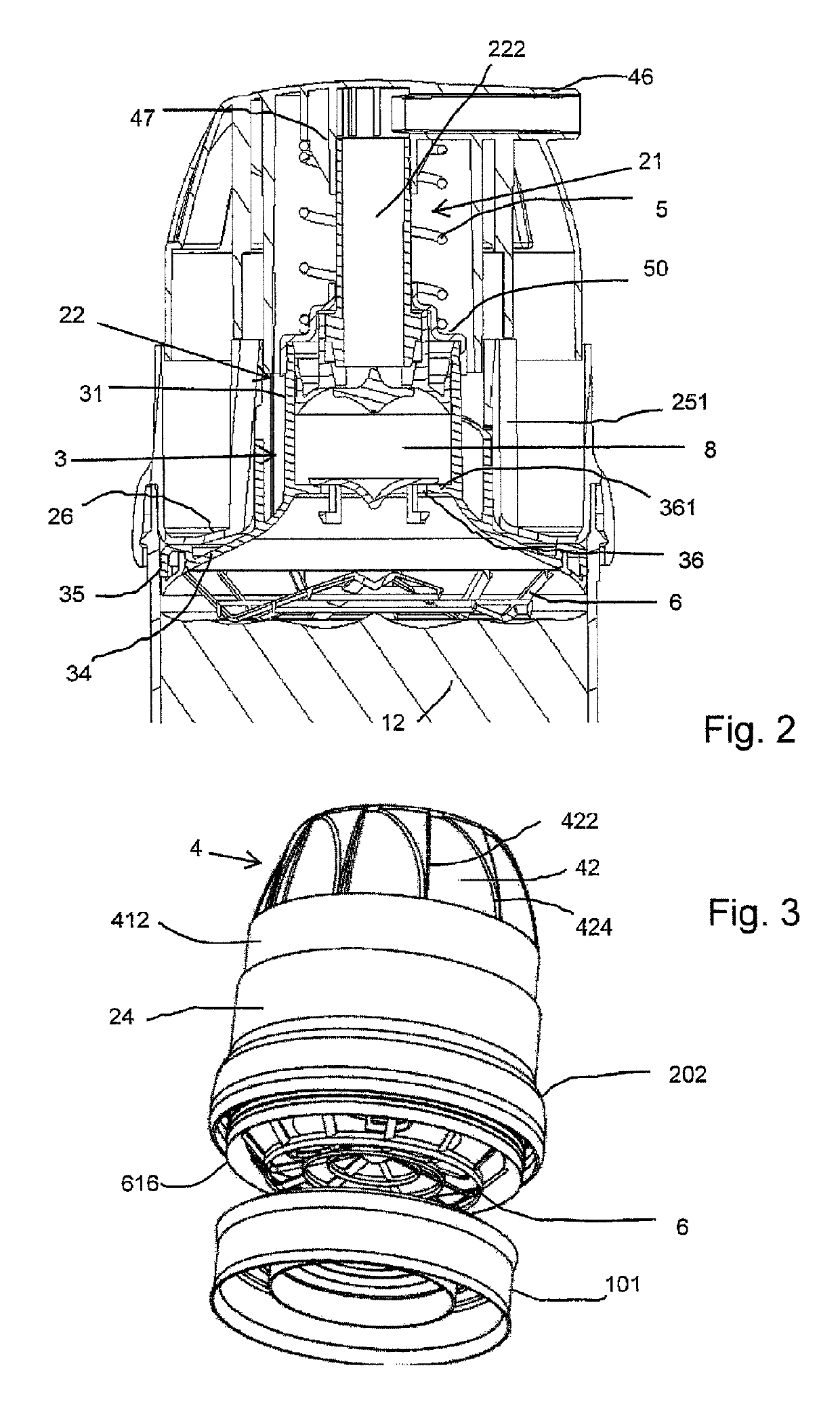
[0091]FIG. 1 shows a container 10 with a cylindrical side wall 105, containing a product 12 which may be an ointment having pseudoplastic properties. The product space is bounded at the b...


PUM


Abstract

A dispenser for dispensing a flowable product from a container has a pump module mounted on the container at an opening thereof. The pump module includes a pump body, which defines a pump chamber and a pump chamber inlet for product to flow from the container interior into the pump chamber. A pump actuator is operable in a pumping stroke relative to the pump body to vary the volume of the pump chamber and dispense the product. The pump includes a movable body portion which is operable in a displacement stroke into the container. The movable portion has a displacement body with a product-engaging face directed onto an interior product space of the container upstream of the pump chamber inlet, to assist priming. Below this a disrupter member, a grid of narrow bars, projects to penetrate the product.

Description

CROSS REFERENCE TO RELATED APPLICATIONS[0001]This application is a continuation of PCT / EP2015 / 074265 filed Oct. 20, 2015, which claims the benefit of U.S. Provisional Application No. 62 / 065,971 filed Oct. 20, 2014, which are hereby incorporated by reference.FIELD OF THE INVENTION[0002]This invention relates to dispensers for use in dispensing flowable products, and to methods of use thereof. The present proposals are particularly but not exclusively concerned with dispensers adapted for use with flowable products that are difficult or even impossible to dispense using conventional dispenser pumps, because they resist flow.BACKGROUND OF THE INVENTION[0003]Pump dispensers having a pump mounted on a container are widely used for dispensing fluid products (liquids, creams, pastes) such as medicaments, bathroom products and cosmetics. Generally, a dispenser comprises a container for the product and a pump module mounted on the container at an opening thereof. The pump module comprises a ...

Claims


Application Information

Patent Timeline
Patent Type & Authority Patents(United States)
IPC IPC(8): B05B11/00B05B15/20B05B15/25
CPCB05B11/3025B05B11/3067B05B11/00418B05B11/3061B05B11/00416B05B15/25B05B15/20B05B11/3059B05B11/028B05B11/1025B05B11/1059B05B11/1061B05B11/1067B05B1/34B05B11/029
Inventor KNIGHT, SIMON CHRISTOPHERPRITCHETT, DAVID JOHNKASTING, THOMAS P.BOX, MARK EDWARDYU, RAYMOND
Owner RIEKE PACKAGING SYST LTD
Why Eureka
Try Eureka