Door closer

a door closer and door technology, applied in the field of door closers, can solve the problems of difficult and problematic adjustment of valve settings in such a conventional door closer, and achieve the effect of slowing/quickening the door closing speed

Active Publication Date: 2016-01-28
ASSA ABLOY ACCESSORIES & DOOR CONTROLS GRP INC
View PDF16 Cites 35 Cited by
  • Summary
  • Abstract
  • Description
  • Claims
  • Application Information

AI Technical Summary

Benefits of technology

[0016]The door position sensor may be a potentiometer or rotary encoder, and the processor may receive input from the potentiometer or rotary encoder for determining the door position and the closing speed of the door. The position sensor may operate by sensing proximity of a magnet or may comprise a Hall effect device.
[0017]The door closer may include a potentiometer that controls electrical resistance across the motor / generator or other means for varying input and / or output power to / from the motor / generator to control the rotation of the electric motor and slow / quicken the closing speed of the door. The processor may be programmed to control the potentiometer or other means of control to automatically adjust the closing speed of the door.

Problems solved by technology

However all configurations have less force available in the closing direction than was required to open the door due to mechanical losses of the system.
Additionally the force must be set high enough to close the door under adverse conditions, such as stack pressure, leading to even higher forces required to open the door at times when the adverse conditions are not present.
Adjusting the valve settings in such a conventional door closer can be difficult and problematic since closing times can vary because of the systems dependency on temperature, pressure, wear, and installation configuration.
Moreover, adjusting the valve settings in order to achieve a desired closing profile for a door can be burdensome for at least some users.
Many door closers exhibit much less than ideal closing characteristics because users are either unwilling or unable to adjust and re-adjust the valve settings in a desired manner or are unaware that the settings can and may need to be changed in order to effectuate a desired closing profile in the face of temperature changes, wear over time, and / or modifications to the physical installation

Method used


Image

  • Door closer
  • Door closer
  • Door closer

Examples


Embodiment Construction

)

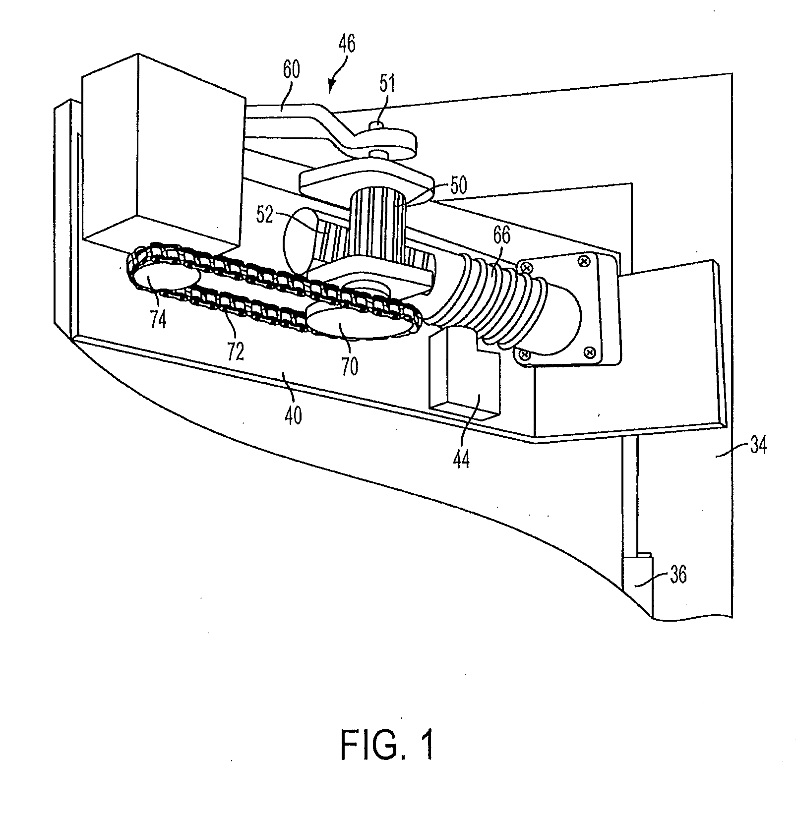
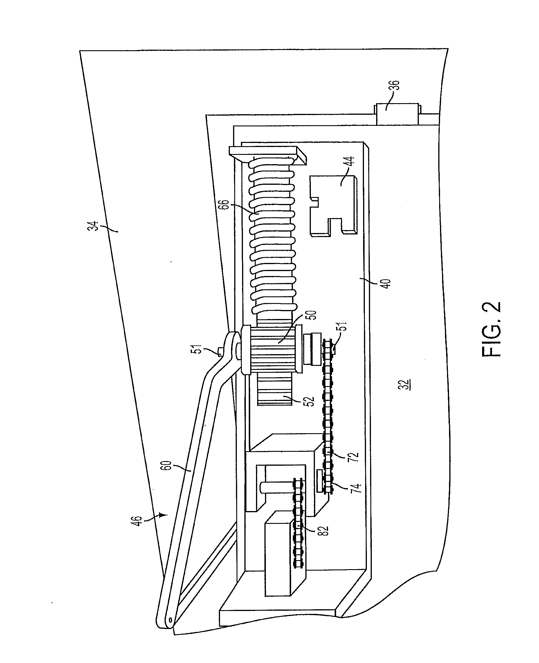
[0050]In describing the preferred embodiment of the present invention, reference will be made herein to FIGS. 1-14 of the drawings in which like numerals refer to like features of the invention. Other embodiments having different structures and operation do not depart from the scope of the present disclosure.

[0051]Certain terminology is used herein for convenience only and is not to be taken as a limitation on the embodiments described. For example, words such as “top”, “bottom”, “upper,”“lower,”“left,”“right,”“horizontal,”“vertical,”“upward,” and “downward” merely describe the configuration shown in the figures. Indeed, the referenced components may be oriented in any direction and the terminology, therefore, should be understood as encompassing such variations unless specified otherwise.

[0052]As used herein, the term “open position” for a door means a door position other than a closed position, including any position between the closed position and a fully open position as limite...


PUM


Abstract

A door closer with an electric motor-assisted closing feature, that may generate its own power to assist in closing, and controls the speed of opening and closing of the door during generation is disclosed. Embodiments of the present disclosure are realized by a motorized door closer that electrically creates a latch boost force for a closing door. The door closer includes a motor disposed to operatively connect to a door so that the door will moved toward closed when the motor moves, and a position sensor to determine a position of the door. A processor is programmed to exert a closing force on the door in the latch boost region or when it otherwise detects that a motor assist is needed.

Description

BACKGROUND OF THE INVENTION[0001]1. Field of the Invention[0002]Aspects of the present disclosure may relate to door closers for automatic closing of doors, and in particular may relate to door closers with a latch boost feature and that may be regenerative.[0003]2. Description of Related Art[0004]Door closers are used to automatically close doors, hold doors open for short intervals, and control opening / closing speeds in order to facilitate passage through a doorway and to help ensure that doors are not inadvertently left open. A door closer is often attached to the top or bottom of a door, and when the door is opened and released, the door closer generates a mechanical force that causes the door to automatically close without any user input. Thus, a user may open a door and pass through its doorway without manually closing the door.[0005]Many conventional door closers are designed such that when opened a spring is compressed and energy is stored in the spring. When the door is all...

Claims


Application Information

Patent Timeline
Patent Type & Authority Applications(United States)
IPC IPC(8): E05F15/611E05F15/79H02P7/24
CPCE05F15/611H02P7/24E05F15/79E05F15/70E05Y2900/132E05Y2800/113E05Y2201/412E05Y2400/514E05Y2400/564E05Y2400/612E05Y2400/616E05F15/60E05F15/63E05Y2400/302E05Y2400/614E05F1/105
Inventor HOUSER, BLUELAWHON, DUSTIN E.ZASOWSKI, PETER E.
Owner ASSA ABLOY ACCESSORIES & DOOR CONTROLS GRP INC
Why Eureka
Try Eureka