Hydraulic shock absorber

a technology of shock absorber and shock absorber, which is applied in the direction of shock absorber, damper-spring combination, vibration damper, etc., can solve the problem of increasing the damage force generated by the main valv

Active Publication Date: 2005-12-01
NISSAN MOTOR CO LTD +1
View PDF10 Cites 35 Cited by
  • Summary
  • Abstract
  • Description
  • Claims
  • Application Information

AI Technical Summary

Benefits of technology

[0008] In this hydraulic shock absorber, when the main valve is closed, the flow path area of the back-pressure chamber inlet passage is kept small (including zero) by the valve mechanism. Therefore, in a low speed region of the piston speed, the pressure in the back-pressure chamber will not rise. Consequently, the back pressure acting on the main valve is small, and damping force can be made sufficiently small. As the main valve opens in accordance with the rise in the piston speed, the flow path area of the back-pressure chamber inlet passage increases, and the pressure in the back-pressure chamber increases. Consequently, damping force generated by the main valve increases. By adjusting the pressure in the back-pressure chamber in this way, the degree of freedom for setting damping force characteristics can be increased to obtain appropriate damping force characteristics. In addition, the damping force generating mechanism can be simplified in structure and reduced in size.
[0010] The hydraulic shock absorber is provided with a relief valve for relieving the pressure from the back-pressure chamber. The relief valve opens when the piston speed rises further and consequently the pressure in the back-pressure chamber reaches a predetermined pressure. Thus, it is possible to suppress an excessive rise in damping force generated by the main valve.
[0012] The hydraulic shock absorber has an elastic seal member integrally secured to the main valve to define the back-pressure chamber. Therefore, it is possible to improve the sealing properties of the back-pressure chamber between the elastic seal member and the main valve. In addition, the assemble ability of the damping force generating mechanism can be improved.
[0014] With this hydraulic shock absorber, an orifice area when the valve mechanism is closed can be set simply by providing at least one orifice in a portion of the piston on which the main valve liftably rests such that the orifice extends from the outer peripheral edge of the portion of the piston to the inner peripheral edge thereof. Thus, it is possible to suppress variations in the orifice area and hence possible to obtain stable orifice characteristics.

Problems solved by technology

Consequently, damping force generated by the main valve increases.

Method used


Image

  • Hydraulic shock absorber
  • Hydraulic shock absorber
  • Hydraulic shock absorber

Examples


first embodiment

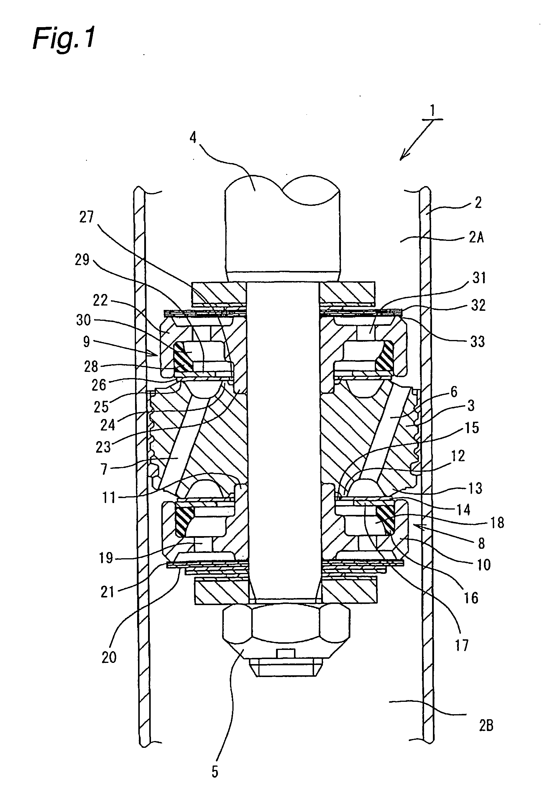
[0054] The above-described arrangement offers advantageous effects similar to those in the foregoing Further, because the main disk valves 14 and 26 and the oil seals 35 and 36 are secured to each other, respectively, sealing performance between these members can be enhanced. Hence, the sealing properties of the back-pressure chambers 18 and 30 can be improved. In addition, it is possible to improve the assembleability of these constituent members to the extension and compression damping force generating mechanisms 8 and 9.

[0055] Next, a third embodiment of the present invention will be described with reference to FIG. 3. It should be noted that in the third embodiment, members or portions that are similar or equivalent to those of the foregoing first embodiment are denoted by the same reference numerals as those used in the first embodiment, and only the portions in which the third embodiment differs from the first embodiment will be explained in detail.

[0056] In a hydraulic shoc...

fourth embodiment

[0059] In a hydraulic shock absorber 42 the main disk valves 14 and 26 are flexible and clamped at their inner peripheral portions between the respective valve members 10 and the piston 3. The main disk valves 14 and 26 open by deflecting. A notched disk 43 as shown in FIG. 6 and a blocking disk 45 as shown in FIG. 5 are stacked in the order mentioned at the side of the main disk valve 14 closer to the extension hydraulic fluid passage 6 (i.e. at the upstream side of the main disk valve 14). Similarly, a notched disk 44 as shown in FIG. 6 and a blocking disk 46 as shown in FIG. 5 are stacked in the order mentioned at the side of the main disk valve 26 closer to the compression hydraulic fluid passage 7 (i.e. at the upstream side of the main disk valve 26). As shown in FIG. 7 or 8, the main disk valves 14 and 26 have circumferentially extending arcuate openings 47 and 48 provided in respective portions closer to the inner peripheries thereof. The notched disks 43 and 44 are each pro...

third embodiment

[0061] The above-described arrangement offers advantageous effects similar to those in the foregoing Further, in this embodiment, back-pressure chamber inlet passages (upstream orifices) for controlling a very small amount of flow are formed by the T-shaped notches 49 and 50 of the notched disks 43 and 44. Accordingly, a desired flow path area when the main disk valve 14 (26) is closed can be set easily by appropriately varying the width, thickness and number of notches 49 (50). Thus, it becomes easy to control the dimensional accuracy and hence possible to obtain stable damping force having minimal variations.

[0062] It should be noted that in the above-described fourth embodiment, the notched disks 43 and 44 may be integrated with the main disk valves 14 and 26, respectively, so that when the main disk valve 14 (26) opens, the notched disk 43 (44) separates from the blocking disk 45 (46), thereby increasing the effective flow path area of the back-pressure chamber inlet passage.

[...


PUM


Abstract

In the disclosed hydraulic shock absorber, the flow of hydraulic fluid induced in each of extension and compression hydraulic fluid passages by sliding movement of a piston is controlled by a main disk valve to generate damping force. The valve opening pressure of the main disk valve is adjusted by the pressure in a back-pressure chamber. In a low piston speed region, the main disk valve closes a back-pressure chamber inlet passage. Therefore, the pressure in the back-pressure chamber will not rise, and sufficiently small damping force is obtained. When the main disk valve opens, the back-pressure chamber inlet passage opens simultaneously. Consequently, the pressure in the back-pressure chamber rises, and the damping force increases.

Description

BACKGROUND OF THE INVENTION [0001] The present invention relates to a hydraulic shock absorber suitable for use in a suspension system of a vehicle, for example, an automobile. [0002] In general, a cylinder type hydraulic shock absorber attached to a suspension system of a vehicle, e.g. an automobile, includes a cylinder having a hydraulic fluid sealed therein. A piston is slidably fitted in the cylinder. The piston is connected with a piston rod to form a piston assembly. The piston assembly is provided with damping force generating mechanisms each including a hydraulic fluid passage, an orifice, a disk valve, etc. The hydraulic fluid is induced to flow through the hydraulic fluid passage by sliding movement of the piston in the cylinder caused by the stroke of the piston rod. The flow of the hydraulic fluid is controlled by the orifice and the disk valve to generate damping force. In a low speed region of the piston speed, damping force is generated by the orifice. In a high pisto...

Claims


Application Information

Patent Timeline
Patent Type & Authority Applications(United States)
IPC IPC(8): F16F9/348
CPCF16F9/3485
Inventor KATOU, HAJIMENAKAJIMA, HIKARUNAKADATE, TAKAO
Owner NISSAN MOTOR CO LTD
Why Eureka
Try Eureka