Photo-voltaic panel retention apparatus, system and method

a technology of photovoltaic panels and racking frames, applied in the field of photovoltaic panel retention apparatuses, systems and methods, can solve the problems of increasing the cost of manufacturing and assembly, and the cost of manufacturing and installation, so as to eliminate the need for expensive racking frames and systems, time and the cost of components and installation costs

Active Publication Date: 2019-11-05
PMC IND
View PDF13 Cites 10 Cited by
  • Summary
  • Abstract
  • Description
  • Claims
  • Application Information

AI Technical Summary

Benefits of technology

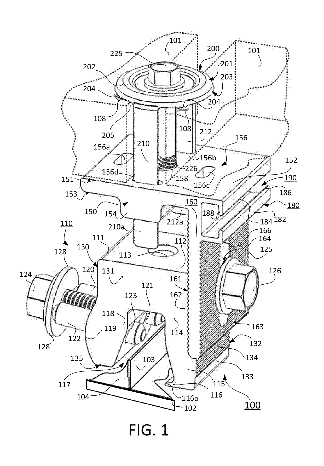
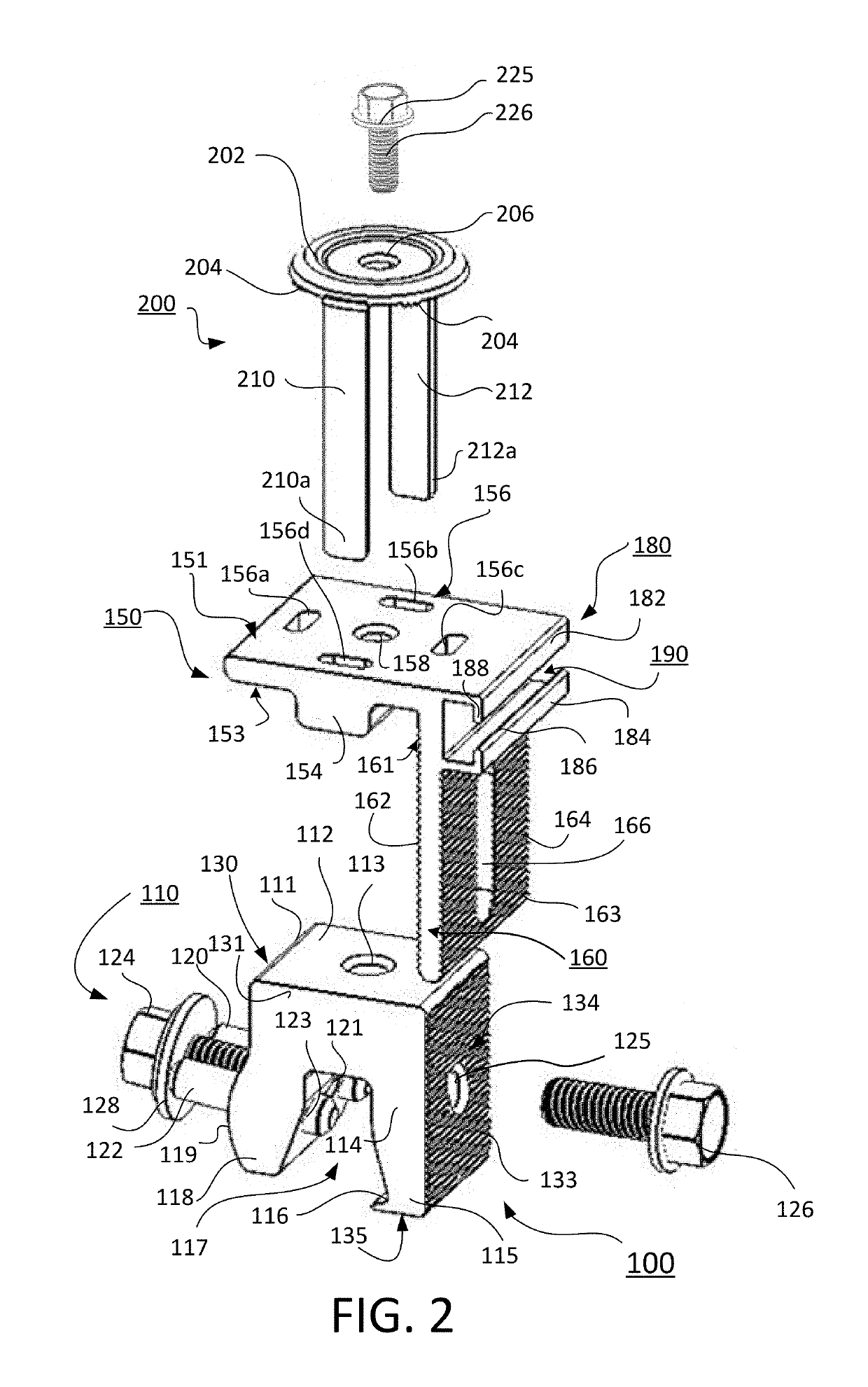
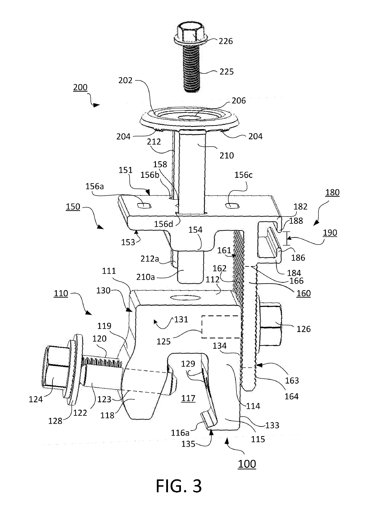
[0004]It is an object of the present invention to provide a photovoltaic panel retention system and method that utilizes a solar cap with one or more integral elongated flange extensions of a predetermined dimension (1) to provide spacing between PV solar panels, (2) to stabilize the solar cap from tipping under installation forces and load in use.
[0006]It is an object of the present invention to provide a photovoltaic panel retention system and method that utilizes a support bracket of a general L-shape configured with a base portion to support adjacent PV panels in a PV panel array using a base platform portion. It is an object of the present invention to eliminate the need for expensive racking frames and systems, time and the component part and installation expense, whereby the PV panel retention apparatus system can use a rail and / or posted-base support systems.

Problems solved by technology

Conventional assemblies and methods for mounting a photovoltaic (PV) panel and other objects on a wall, rooftop and other structure generally involve numerous parts that increase the cost of manufacturing the assembly and its price.
Similarly these conventional standing seam assemblies and systems require numerous parts and assemblies that add cost to the manufacture and installation.
Consequently, conventional assemblies are costly to manufacture as well as installation time is increased because of the assembly required on-site that adds time on the roof for the installer and overall costs for the installation.

Method used


Image

  • Photo-voltaic panel retention apparatus, system and method
  • Photo-voltaic panel retention apparatus, system and method
  • Photo-voltaic panel retention apparatus, system and method

Examples


Embodiment Construction

[0016]Non-limiting embodiments of the present invention will be described below with reference to the accompanying drawings, wherein like reference numerals represent like elements throughout. While the invention has been described in detail with respect to the preferred embodiments thereof, it will be appreciated that upon reading and understanding of the foregoing, certain variations to the preferred embodiments will become apparent, which variations are nonetheless within the spirit and scope of the invention.

[0017]The terms “a” or “an”, as used herein, are defined as one or as more than one. The term “plurality”, as used herein, is defined as two or as more than two. The term “another”, as used herein, is defined as at least a second or more. The terms “including” and / or “having”, as used herein, are defined as comprising (i.e., open language). The term “coupled”, as used herein, is defined as connected, although not necessarily directly, and not necessarily mechanically.

[0018]R...


PUM


Abstract

The invention relates to retention systems and, more particularly, for a modular retention apparatus, system and method for securing and leveling a photovoltaic (PV) panel and other objects on a wall, rooftop and other structure to secure and ground electrically. The photovoltaic panel retention assembly utilizes a solar cap with one or more integral elongated flange extensions of a predetermined dimension to provide spacing between PV solar panels and / or to stabilize the solar cap from tipping under installation forces and load in use. The flanges extend through a support bracket configured with a base portion to support adjacent PV panels in a PV panel array and a base platform portion. The solar cap comprises integral teeth on a surface of the solar cap spaced apart from the flanged projections to locate the teeth adjacent a frame of the PV panel for electrical grounding thereof.

Description

FIELD OF THE INVENTION[0001]The present invention relates to retention systems and, more particularly, for a modular retention apparatus, system and method for securing and leveling a photovoltaic (PV) panel and other objects on a wall, rooftop and other structure to secure and ground electrically.BACKGROUND OF THE INVENTION[0002]Conventional assemblies and methods for mounting a photovoltaic (PV) panel and other objects on a wall, rooftop and other structure generally involve numerous parts that increase the cost of manufacturing the assembly and its price. This applies to conventional assemblies designed for a roof structure, e.g. a metal roof with a standing seam. Similarly these conventional standing seam assemblies and systems require numerous parts and assemblies that add cost to the manufacture and installation. Consequently, conventional assemblies are costly to manufacture as well as installation time is increased because of the assembly required on-site that adds time on t...

Claims


Application Information

Patent Timeline
Patent Type & Authority Patents(United States)
IPC IPC(8): H02S20/10H02S20/23E04D3/30H01L31/042
CPCH02S20/10H02S20/23E04D3/30H01L31/042Y02B10/12F24S25/35F24S25/636F24S2025/6003F24S2025/6008H02S30/00H02S40/30Y02B10/10Y02B10/20Y02E10/47Y02E10/50
Inventor KOVACS, TAMAS
Owner PMC IND
Why Eureka
Try Eureka