

Dynamic determination of a minimal configured product to achieve desired test coverage
a technology of configuration and product, applied in the field of product manufacturing, can solve the problems of insufficient approaches, overpowering the simple logic of either approach, and affecting the test coverage of the product, so as to reduce the test cycle time, reduce the cost and expense of capital inventory, and increase the test coverage/quality
- Summary
- Abstract
- Description
- Claims
- Application Information
AI Technical Summary
Benefits of technology
Problems solved by technology
Method used
Image

Examples
Embodiment Construction
Reference will now be made in detail to the subject matter disclosed, which is illustrated in the accompanying drawings.
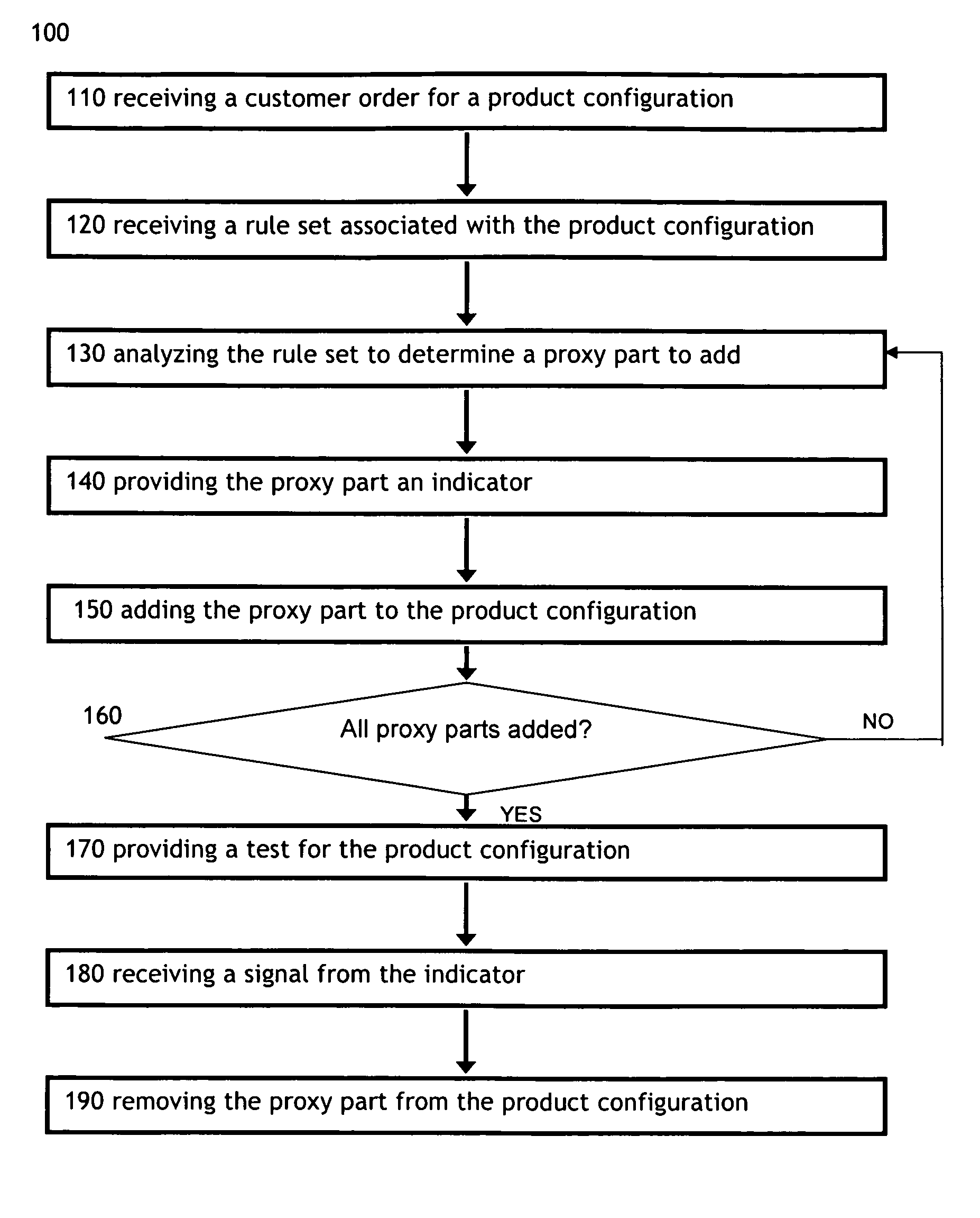
The present disclosure is directed to a method for determining dynamic test coverage for a product. The method may comprise: receiving a customer order, the customer order comprising at least one product configuration; receiving a rule set associated with the at least one product configuration; analyzing the rule set to determine a proxy part to add to the at least one product configuration; providing the proxy part an indicator, wherein the indicator transmits a signal to indicate the proxy part should be removed from the at least one product configuration; adding the proxy part to the at least one product configuration; iteratively comparing the product configuration to the rule set until the product configuration meets the rule set; providing a test associated with the at least one product configuration; receiving at least one signal from at least one indicator;...
PUM
 Abstract
Description
Claims
Application Information