
Digital device for improving image quality with low power and control method thereof

a digital device and image quality technology, applied in the field of digital devices, can solve the problems of reducing power consumption of digital devices is proportional, and image quality degradation, so as to reduce power consumption, improve contrast and sharpness of images, and minimize image quality degradation

Active Publication Date: 2019-11-05
LG ELECTRONICS INC +1
View PDF15 Cites 0 Cited by
  • Summary
  • Abstract
  • Description
  • Claims
  • Application Information

AI Technical Summary

Benefits of technology

The present invention provides a method to improve image quality while reducing power consumption. The method involves a pre-processing process to enhance contrast and sharpness and a post-processing process to divide the screen and adjust maximum pixel value. Additionally, the method allows users to set a target power saving amount, providing better user convenience. The technical effects of this invention include minimizing image quality degradation and reducing power consumption while improving overall image quality.

Problems solved by technology

However, as the digital devices become larger, power consumption is also increased.
That is, power consumption of the digital device is proportional to brightness of a light source used as backlight and the brightness of the light source depends on a pixel value of an image to be displayed.
However, the method has the following problems.
That is, contrast and sharpness of an image is decreased due to a decreased dynamic range of the image and thus, overall image quality is degraded.
According to the method, although a certain level of the image brightness and contrast can be secured, the brightness may be changed at an area boundary in case of using a local dimming scheme where the brightness of the light source is adjusted by using the maximum pixel value of the image in a non-uniform manner, which causes problems that artifacts occur and details of a bright part disappear.

Method used


Image

  • Digital device for improving image quality with low power and control method thereof
  • Digital device for improving image quality with low power and control method thereof
  • Digital device for improving image quality with low power and control method thereof

Examples


Embodiment Construction

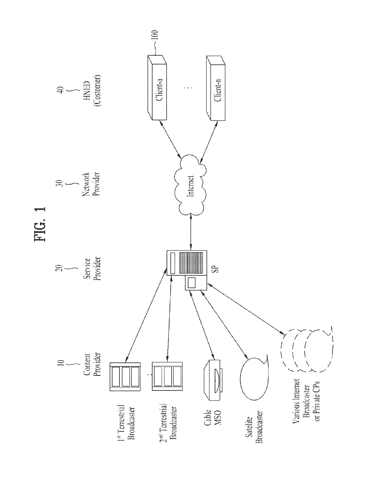
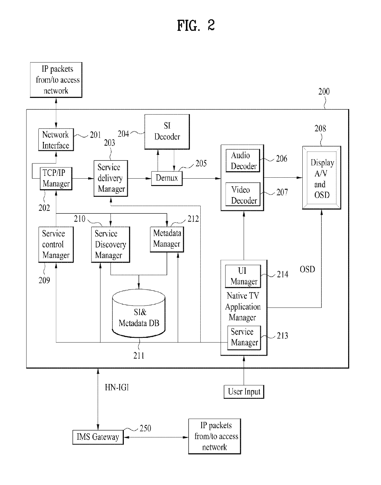
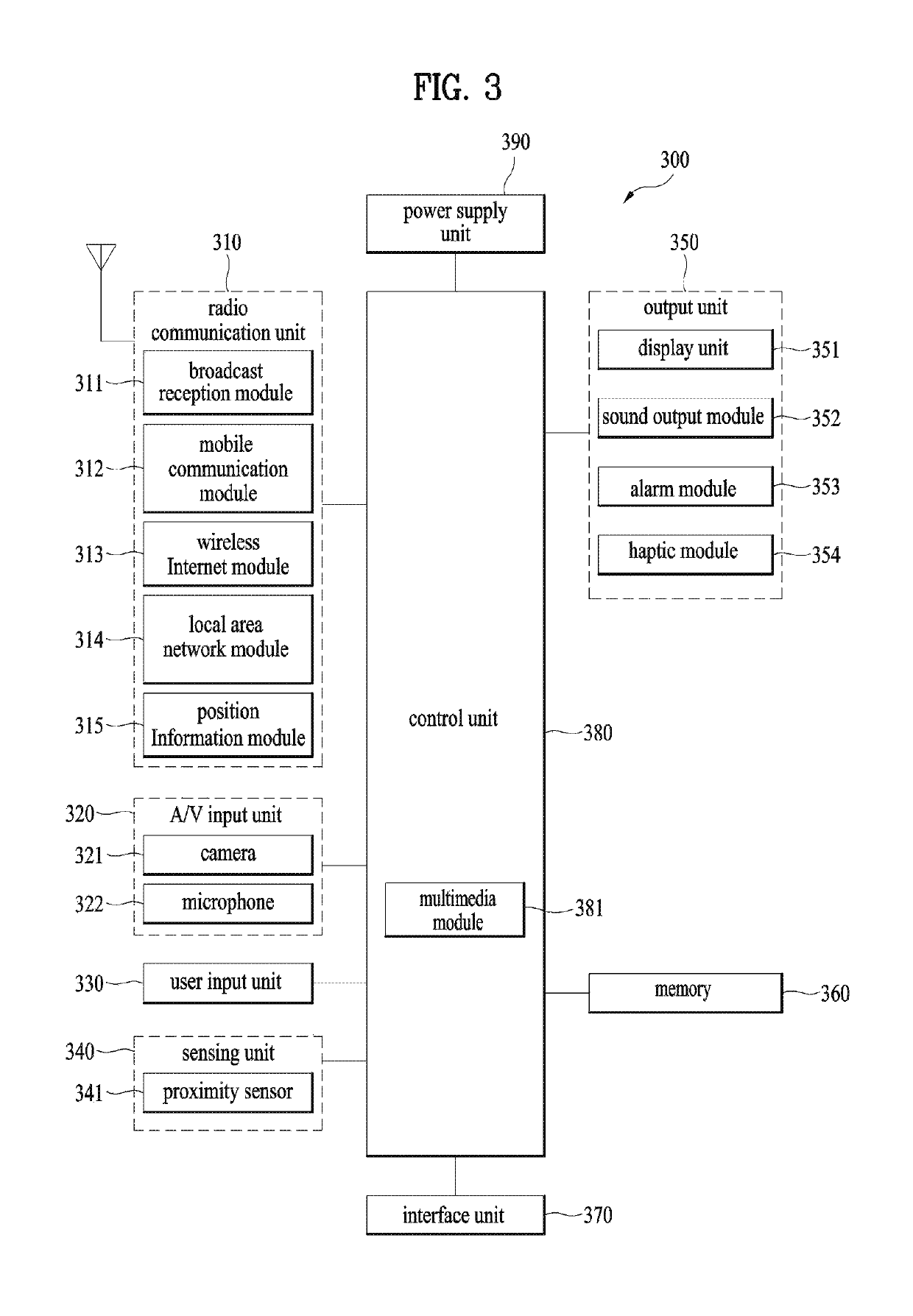
[0031]Description will now be given in detail according to exemplary embodiments disclosed herein, with reference to the accompanying drawings.

[0032]In general, a suffix such as “module” and “unit” can be used to refer to elements or components. Use of such a suffix herein is merely intended to facilitate description of the specification, and the suffix itself is not intended to give any special meaning or function. Meanwhile, such an ordinal number as ‘first, ‘second’, ‘third’ and the like can have a meaning of an order. Yet, the terminologies can be used for the purpose of distinguishing one component from another component capable of being overlapped with each other. In the present disclosure, that which is well-known to one of ordinary skill in the relevant art has generally been omitted for the sake of brevity.

[0033]The accompanying drawings are used to help easily understand various technical features and it should be understood that the embodiments presented herein are not li...


PUM


Abstract

A digital device and a control method thereof are disclosed in the present specification. The digital device and the control method thereof according to the present invention may comprise the steps of receiving an image signal; separating the received image signal by a plurality of frequency bands; adjusting a gain for the image signal of each of the separated frequency bands; displaying an enhanced image on a screen by synthesizing the image signals of the respective frequency bands in which the gain has been adjusted; separating the screen, on which the enhanced image is displayed, into a plurality of areas; checking whether the maximum pixel value of the enhanced image displayed on the separated screen area, if the maximum pixel value of the enhanced image is larger than the reference value.

Description

CROSS-REFERENCE TO RELATED APPLICATIONS[0001]This application is the National Stage filing under 35 U.S.C. 371 of International Application No. PCT / KR2015 / 002751, filed on Mar. 20, 2015, which claims the benefit of earlier filing date and right of priority to Korean Application No. 10-2014-0160958, filed on Nov. 18, 2014, the contents of which are all hereby incorporated by reference herein in their entirety.TECHNICAL FIELD[0002]The present invention relates to a digital device, and more particularly, a digital device for improving image quality with low power and control method thereof.BACKGROUND ART[0003]Recently, digital devices including a monitor, a TV, and the like have become larger and been widely used. However, as the digital devices become larger, power consumption is also increased. Accordingly, a digital device capable of reducing power consumption to save energy without degradation in image quality needs to be developed.[0004]In a digital device such as an LCD device, m...

Claims


Application Information

Patent Timeline
Patent Type & Authority Patents(United States)
IPC IPC(8): H04N5/52H04N5/57H04N21/4402H04N5/63H03G3/20H04N5/44H04N21/443
CPCH03G3/20H04N5/52H04N5/63H04N5/4401H04N5/57H04N21/4436H04N21/440245H03G5/165Y02B70/10H04N21/426
Inventor WOO, HUNBAELEE, CHEOLJOOSONG, BYUNGCHEOLNAM, YEONOHCHOI, DONGYOON
Owner LG ELECTRONICS INC
Learn More