Liquid ejection head, liquid ejection apparatus, and method of attaching liquid ejection head

a liquid ejection and liquid ejection technology, which is applied in the direction of power drive mechanisms, printing, inking apparatus, etc., can solve the problems of electrical short circuit, difficult to satisfactorily connect both the connection parts simultaneously, and parts may be displaced, so as to achieve convenient and efficient connection

Active Publication Date: 2019-11-12
CANON KK
View PDF30 Cites 0 Cited by
  • Summary
  • Abstract
  • Description
  • Claims
  • Application Information

AI Technical Summary

Benefits of technology

[0007]In such circumstances, the present invention is intended to provide a liquid ejection head that enables easy and efficient connection for liquid and electrical connection and can prevent a liquid scattered from a connection part for liquid from adhering to an electrical connector, a liquid ejection apparatus, and a method of attaching a liquid ejection head.

Problems solved by technology

However, if these connection parts are spaced apart from each other, one connection part may be at a correct position, but the other connection part may be displaced from a correct position, due to inclination of the attachment posture of the liquid ejection head, for example.
As a result of such a positional displacement, it may be difficult to satisfactorily, simultaneously connect both the connection parts.
If the scattered liquid adheres to an electrical connector, electrical short-circuit may be caused or the electric reliability may be affected.
Meanwhile, in such a structure using a flexible cable for electrical connection as in Japanese Patent Application Laid-Open No. 2016-175282, a scattered liquid is unlikely to adhere to the electrical connector.
However, the electrical connection using a flexible cable requires meticulous operations and is required to be performed completely separately from connection of a connection part for liquid or from install and removal of a liquid ejection head.
This complicates the operation to reduce the efficiency.

Method used


Image

  • Liquid ejection head, liquid ejection apparatus, and method of attaching liquid ejection head
  • Liquid ejection head, liquid ejection apparatus, and method of attaching liquid ejection head
  • Liquid ejection head, liquid ejection apparatus, and method of attaching liquid ejection head

Examples


Embodiment Construction

[0018]Preferred embodiments of the present invention will now be described in detail in accordance with the accompanying drawings.

[0019]Embodiments of the present invention will now be described with reference to drawings.

[0020][Liquid Ejection Head]

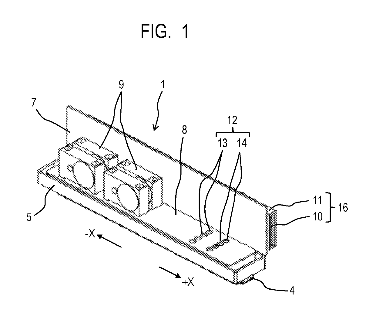
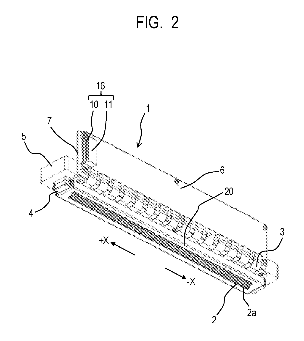
[0021]FIG. 1 is a perspective view of a long-length liquid ejection head 1 in a first embodiment of the present invention, viewed from the top side. FIG. 2 is a perspective view of the liquid ejection head 1 viewed from the bottom side. The liquid ejection head 1 of the embodiment is an ink jet recording head, and the liquid ejection apparatus of the embodiment is an ink jet recording apparatus. The liquid ejection head is a page-wide liquid ejection head used in a page-wide liquid ejection apparatus and has, in the longitudinal direction, a dimension not less than the dimension of a liquid ejection object (for example, the recording medium 104 shown in FIG. 5) (a width not less than the width of an object).

[0022]The liquid ejection head...


PUM


Abstract

A page-wide liquid ejection head configured to be removably installed in a main body of a liquid ejection apparatus includes a connection part for liquid through which a liquid is supplied from the main body and an electrical connector through which an electric signal is supplied from the main body. In the liquid ejection head, the connection part for liquid and the electrical connector are located at one side of the liquid ejection head in the longitudinal direction and are provided to face different directions from each other.

Description

BACKGROUND OF THE INVENTIONField of the Invention[0001]The present invention relates to a liquid ejection head, a liquid ejection apparatus, and a method of attaching a liquid ejection head.Description of the Related Art[0002]Liquid ejection apparatuses that eject a liquid for image recording or the like include an apparatus including a long-length liquid ejection head having a dimension corresponding to the width of a liquid ejection object (for example, a recording medium) (page-wide liquid ejection apparatus). The liquid ejection head of the page-wide liquid ejection apparatus ejects a liquid to the full width of an object while not moved but fixed. The liquid ejection apparatus has such characteristics as to enable simultaneous ejection of a large amount of a liquid and high-speed recording by liquid ejection, for example, as compared with a serial scan apparatus having a compact liquid ejection head that ejects a liquid while moving in the width direction of an object.[0003]The...

Claims


Application Information

Patent Timeline
Patent Type & Authority Patents(United States)
IPC IPC(8): B41J2/155B41J2/175B41J25/34B41J2/18
CPCB41J2/17553B41J25/34B41J2/17526B41J2/155B41J2/1753B41J2/18B41J2202/14B41J2202/19B41J2202/20B41J2202/21B41J2202/12B41J2/14072B41J2/14201B41J2/17523B41J29/393B41J2/045
Inventor INADA, GENJIHIROSAWA, TOSHIAKIAMMA, HIROMASAKAWAMURA, SHOGOOSAKI, YASUHIKOISHIMATSU, SHINIWANO, TAKUYA
Owner CANON KK
Why Eureka
Try Eureka