Eureka AIR delivers breakthrough ideas for toughest innovation challenges, trusted by R&D personnel around the world.

Tubular isolation valve resettable lock open mechanism

a technology of lock open mechanism and valve body, which is applied in the direction of sealing/packing, wellbore/well accessories, construction, etc., can solve the problems of affecting the function of the valve further, and affecting the operation of the valve body

Active Publication Date: 2019-11-12
BAKER HUGHES INC
View PDF14 Cites 5 Cited by
  • Summary
  • Abstract
  • Description
  • Claims
  • Application Information

AI Technical Summary

Benefits of technology

[0007]A safety valve features a flow tube operated flapper for the normal open and closed positions that can be obtained with one or two control lines to a principal operating piston. Pressure applied to the piston moves the flow tube to rotate the flapper open behind the flow tube. Release of pressure to the principal piston allows a closure spring to return the flow tube up to let the flapper close. A secondary piston can drive the flow tube with applied pressure through a control line. Cycling the applied pressure in combination with an indexing mechanism allows the flapper to be locked open and then released to normal operation. The pistons act as backup for each other as they both drive the flow tube. The flow tube has a clearance fit to the body in the locked open position to exclude debris from the flapper.

Problems solved by technology

Early designs managed to lock the valve open in such a way that further functionality of the valve was destroyed.
These designs left the flapper open to the flow path where accumulated debris could impede the movement of the hold down mechanism or the flapper.
This design left the flapper exposed to debris in well fluid when locked open.
This complex design has a ratchet exposed to well fluids that can get stuck and fail to release the locking piston from trying to push plate 80 down with the primary piston.
The secondary piston cannot operate the valve at all and further features an array of small parts and springs calling into question its reliability in severe environments.

Method used


Image

  • Tubular isolation valve resettable lock open mechanism
  • Tubular isolation valve resettable lock open mechanism
  • Tubular isolation valve resettable lock open mechanism

Examples


Embodiment Construction

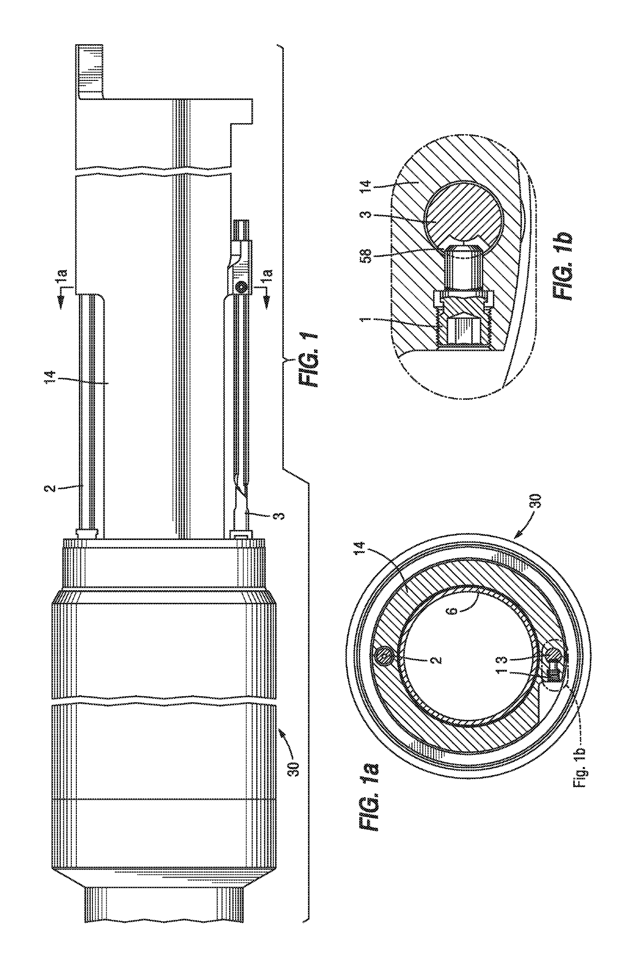
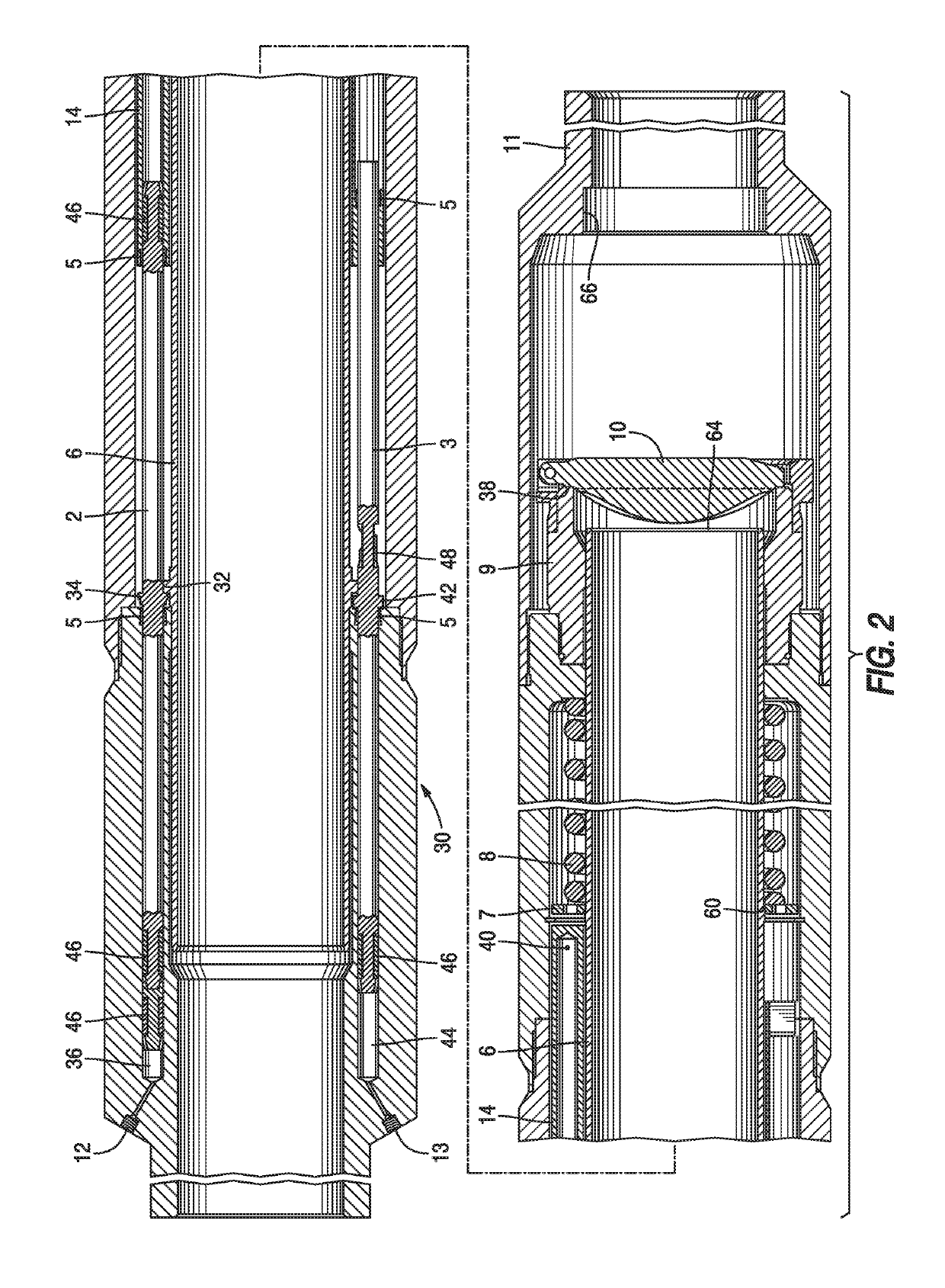
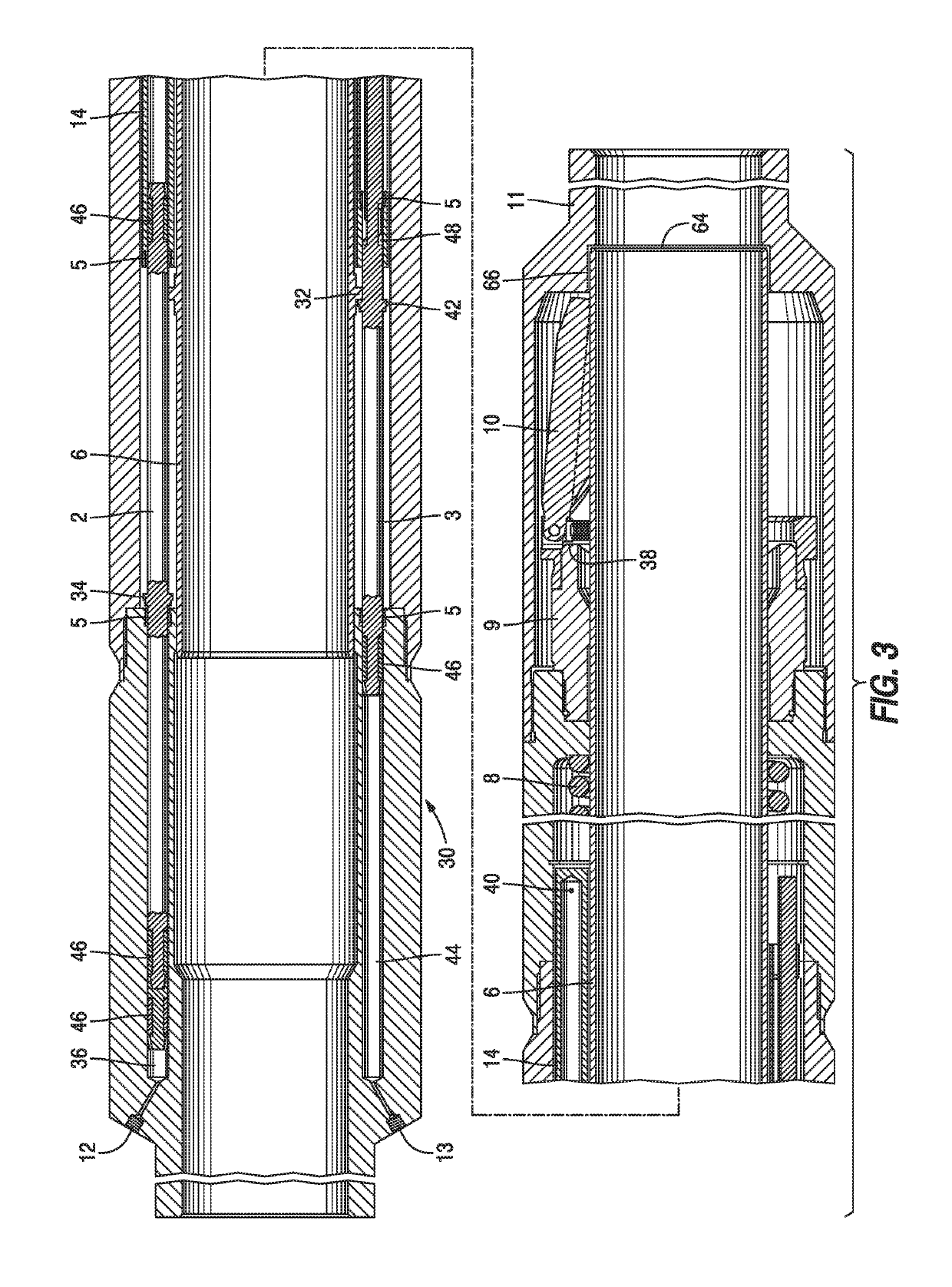
[0019]Referring to FIG. 1 a primary piston 2 and a secondary piston 3 are shown preferably spaced 180 degrees apart on housing 30. The names primary and secondary are used to distinguish the two pistons only as will be apparent from the explanation below where the pistons can be redundant allowing either one to operate the flow tube 6. The basic components of the safety valve are a flapper 10 that is rotated 90 degrees by the flow tube 6. Flow tube 6 has a ring or discrete shoulders 32 as shown in FIG. 2. Primary piston 2 has an external ring 34 that engages ring 32 to move the flow tube 6 against the flapper 10. What drives piston 2 is control line pressure to primary piston connection 12 that is retained by piston seals 46 as chamber 36 enlarges in volume as piston 2 is pushed to the right or toward the flapper 10 which is rotated by the linear movement of flow tube 6 caused by ring 34 pushing ring 32. If the pressure in chamber 36 is relieved the closure spring 8 pushes up on rin...


PUM


Abstract

A safety valve features a flow tube operated flapper for the normal open and closed positions that can be obtained with one or two control lines to a principal operating piston. Pressure applied to the piston moves the flow tube to rotate the flapper open behind the flow tube. Release of pressure to the principal piston allows a closure spring to return the flow tube up to let the flapper close. A secondary piston can drive the flow tube with applied pressure through a control line. Cycling the applied pressure in combination with an indexing mechanism allows the flapper to be locked open and then released to normal operation. The pistons act as backup for each other as they both drive the flow tube. The flow tube has a clearance fit to the body in the locked open position to exclude debris from the flapper.

Description

FIELD OF THE INVENTION[0001]The field of the invention is a tubular string isolation valve and more particularly a flow tube actuated flapper or other type of closure such as a ball (hereinafter collectively called “flapper”) type safety valve that allows the flow tube to be releasably locked to the housing when the flapper is open and released for return to normal operation.BACKGROUND OF THE INVENTION[0002]Safety valves in tubular strings such as a production string in a borehole or a production riser from a subsea wellhead at times need to be held open. Early designs managed to lock the valve open in such a way that further functionality of the valve was destroyed. One example is U.S. Pat. Nos. 7,137,452; 7,703,541 and U.S. Pat. No. 5,598,864. Other designs used a flow through method to open the flapper and combined flow through the passage in cycles of pressure actuation and removal with a j-slot mechanism to hold a flapper open and another cycle to release the flapper for normal...

Claims


Application Information

Patent Timeline
Patent Type & Authority Patents(United States)
IPC IPC(8): E21B34/14E21B34/10E21B23/00E21B34/00
CPCE21B23/006E21B34/14E21B34/10E21B2034/005E21B2200/05E21B34/08E21B34/102
Inventor MILLER, WADE A.BURRIS, JOHN E.
Owner BAKER HUGHES INC
Why Eureka
Eureka Blog
Learn More