Turbopropeller control system with control saturation management

a control system and control saturation technology, applied in the direction of mechanical equipment, machines/engines, transportation and packaging, etc., can solve the problems of complex implementation, limited fuel flow rate wf and screw propeller pitch, and first solution complex implementation

Active Publication Date: 2019-11-19
SN DETUDE & DE CONSTR DE MOTEURS DAVIATION S N E C M A
View PDF9 Cites 0 Cited by
  • Summary
  • Abstract
  • Description
  • Claims
  • Application Information

AI Technical Summary

Problems solved by technology

Moreover, there exist, in a turbopropeller, limits on the fuel flow rate WF and screw propeller pitch β controls imposed by the operating constraints of the turbopropeller.
This first solution is complex to implement.
This second solution is complex to implement and its complexity increases with the number of inputs / outputs.
The prior art solutions for correcting the desynchronization of controls saturated by limiters are therefore not satisfactory.

Method used


Image

  • Turbopropeller control system with control saturation management
  • Turbopropeller control system with control saturation management
  • Turbopropeller control system with control saturation management

Examples


Embodiment Construction

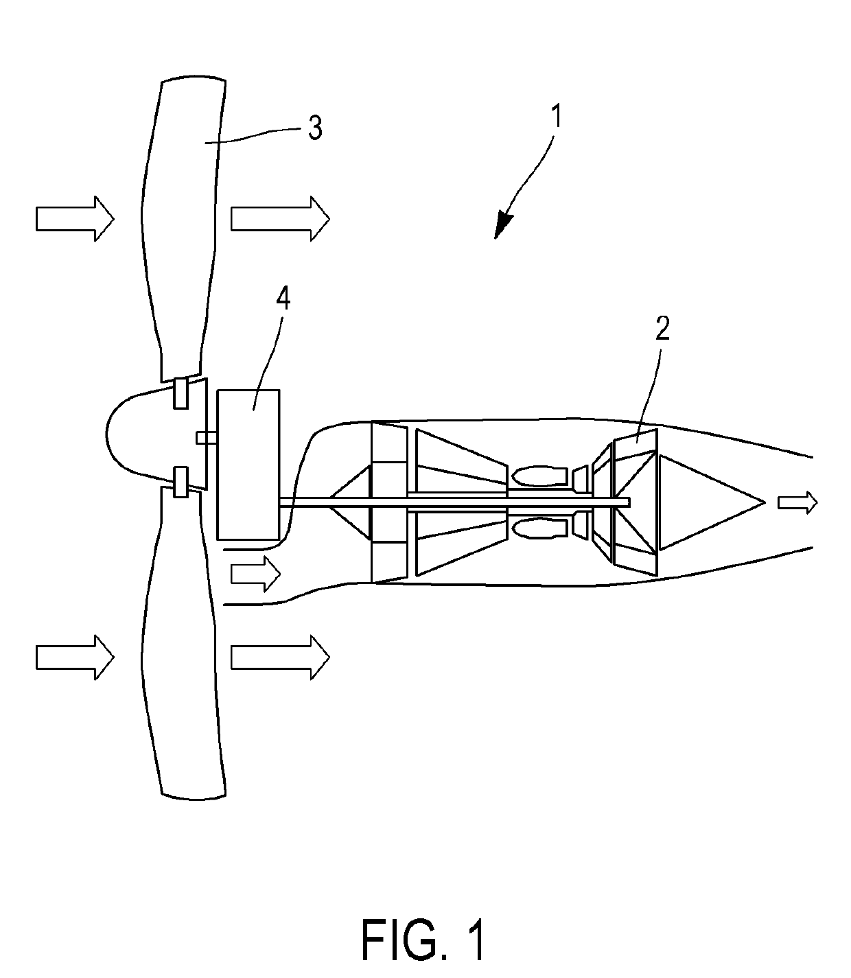
[0101]A turbopropeller control system 10 is an onboard computer synthesizing the screw propeller pitch β and fuel flow rate controls for the turbopropeller 1 based on the screw propeller power and screw propeller rotation set points set by the pilot.

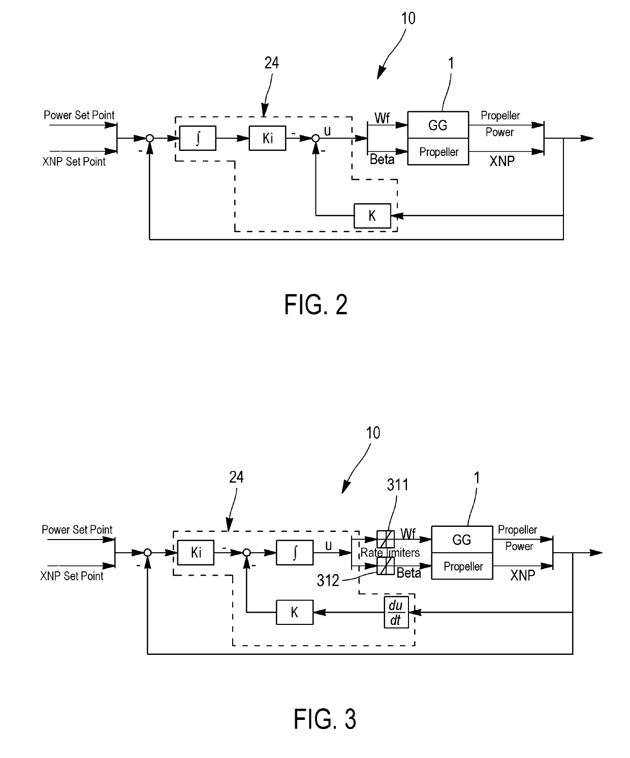
[0102]As illustrated in FIG. 5, the control system 10 of a turbopropeller 1 includes:[0103]a screw propeller torque sensor 27 at the output of the turbopropeller 1;[0104]a screw propeller rotation speed XNP sensor 28 at the output of the turbopropeller 1;[0105]a fuel flow rate control 37 of the turbopropeller;[0106]a screw propeller pitch control 38 of the turbopropeller;[0107]a centralized control 24 configured to slave:[0108]the screw propeller power PRW (calculated as the product of, on the one hand, the torque measured by the sensor 27 and on the other hand the rotation speed measured by the sensor 28) to the screw propeller power set point PRWref, and the screw propeller rotation speed XNP to the screw propeller rotation speed set p...


PUM


Abstract

A control system (10) of a turbopropeller (1) including: a centralized control (24) configured to slave the screw propeller power PRW of the turbopropeller (1) to the screw propeller power set point PRWref and the screw propeller rotation speed XNP of the turbopropeller (1) to the screw propeller rotation speed set point XNPref, the centralized control (24) supplying fuel flow rate WF and screw propeller pitch β controls for the turbopropeller (1); a screw propeller rotation speed error limiter (12) saturating the screw propeller rotation speed error ΔXNP with a limiting valueΔ⁢⁢XNPsat⁡(min⁢ / ⁢max);and a screw propeller power error limiter (11) saturating the screw propeller power error ΔPRW with a limiting valueΔ⁢⁢PRWsat⁡(min⁢ / ⁢max).

Description

FIELD OF THE INVENTION[0001]The invention relates to the field of turbopropeller control systems.PRIOR ART[0002]With reference to FIG. 1, a turbopropeller 1 consists of a turbine 2, driving a variable—pitch screw propeller 3 by means of a reduction gear 4.[0003]With reference to FIG. 2, a turbopropeller can be seen as a multivariable system comprising:[0004]two controls:[0005]the fuel flow rate, which will be denoted WF,[0006]the screw propeller pitch (also called pitch angle), which will be denoted β;[0007]two output variables:[0008]the screw propeller power, which will be denoted PRW,[0009]the speed of rotation of the screw propeller, which will be denoted XNP.[0010]In the case of a centralized control system 24, the turbopropeller control system 10 comprises a multivariable corrector taking into account the screw propeller power PRW and screw propeller rotation speed XNP outputs to synthesize the fuel flow rate WF and screw propeller pitch β controls based on of screw propeller p...

Claims


Application Information

Patent Timeline
Patent Type & Authority Patents(United States)
IPC IPC(8): F02C9/58
CPCF02C9/58F05D2240/35F05D2270/02F05D2220/32F05D2270/053F05D2220/324F05D2270/335B64C11/303B64C11/305
Inventor LIACU, BOGDAN CHRISTIAN
Owner SN DETUDE & DE CONSTR DE MOTEURS DAVIATION S N E C M A
Why Eureka
Try Eureka