
Device for extracting cutting bit from holder

a technology for removing cutting bits and holder, which is applied in the direction of slitting machines, manufacturing tools, metal working apparatuses, etc., can solve the problems of reducing the efficiency of equipment that relies on them, cutting bits exposed to extreme frictional and impact forces, and cutting bits that are inevitable wear and damage, etc., to achieve sufficient lateral dimension and sufficient axial dimension

Active Publication Date: 2019-11-26
VERKLEY STEVEN GERARD
View PDF33 Cites 2 Cited by
  • Summary
  • Abstract
  • Description
  • Claims
  • Application Information

AI Technical Summary

Benefits of technology

Enables rapid and effective separation of cutting bits from their holders or equipment, reducing labor costs and minimizing the risk of damage, while ensuring safe operation by controlling the force applied during extraction.

Problems solved by technology

During the operation of such roadway surface reclaiming machines, the cutting bits are exposed to extreme frictional and impact forces.
Although these bits are typically manufactured from hardened materials, wear and damage to the cutting bits is inevitable.
As the cutting bits wear, the efficiency of the equipment that relies upon them is reduced, slowing the reclamation process and increasing the burdens imposed upon the rutting hit holders, the cutting drums and the equipment that drives these devices.
This leads to delay and increased costs for additional maintenance and labor.
However, typical road surface reclamation devices use a large number of cutting bits, thus, the replacement of the cutting bits is a time consuming process, largely because the manual removal and reinstallation cutting bits is often tedious and slow.
Thus, replacement of the bits is expensive, both requiring the extended attention of one or more trained mechanics, and because all road reclamation operations must cease during replacement of the cutting bits.
When circumstances dictate that cutting bits must be replaced during regularly scheduled reclamation activities, hundreds of labor hours can be lost.
However it is often very difficult to remove cutting bits from cutting bit holders.
Because of this, simply providing a tool that uses substantial amounts of force to separate these components will not meet the design objectives unless this force is properly directed and channeled to prevent damage to the cutting bit holders and the drum.
It is, therefore, necessary that the freedom of motion available to the cutting bit is restricted in order to limit the possibility that the cutting bit will unexpectedly contact the user of the tool, the cutting bit holder or the drum.

Method used


Image

  • Device for extracting cutting bit from holder
  • Device for extracting cutting bit from holder
  • Device for extracting cutting bit from holder

Examples


Embodiment Construction

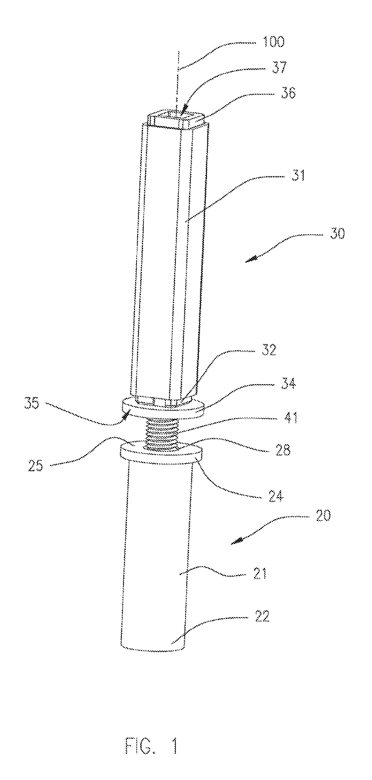
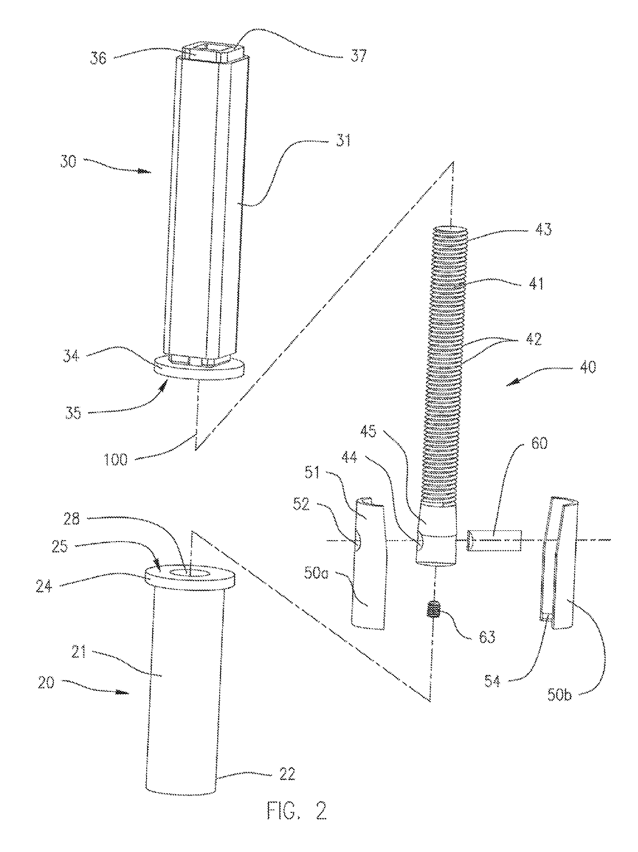
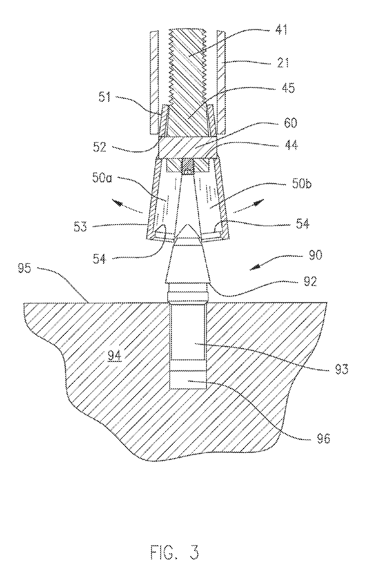
[0032]A tool 10 for separating a cutting bit 90 from an auger 94 is shown in FIGS. 1-3. An auger 94 including cutting bits 90 is shown in FIG. 7. The cutting bit 90 (FIG. 3) has a base end 93 that is inserted into a retaining hole 96 of a cutting bit holder or cutting equipment, illustrated as an auger 94, and an upper end protruding above a surface 95 of a portion of the auger 94, Cutting bits 90 and the auger 94 are known in the prior art. These cutting bits 90 are typically provided with engagement surfaces, such as an annular peripheral groove 92, that provides control surfaces on the cutting bit 90 to facilitate attachment of a gripping element, illustrated as bit jaws 50, for removal of the cutting bit 90 from the auger 94. The bit jaws 50 include an in-turned ledge 54 for engaging and securing into the annular peripheral groove 92 from opposite sides of the cutting bit 90. The in-turned ledge has an arcuate that follows the outer curvature of the wail of the bit jaw 50. The i...


PUM

PropertyMeasurementUnit
circumferenceaaaaaaaaaa
lengthaaaaaaaaaa
diameteraaaaaaaaaa

Abstract

A device for extracting a cutting bit from within a securement hole in cutting equipment. The device has a base body having an open base end that contact the cutting equipment that surrounds the cutting bit. An elongated drive body having a threaded member with a threaded bore, rotatively contacts the base body, and a threaded post having a threaded portion is threaded within the threaded bore of the elongated drive body, and has a lower end extending into the base body. A pair of bit jaws are attached to the lower end of the threaded post, each having an in-turned ledge for engaging a peripheral groove of the cutting bit. By rotating the drive body, the threaded post is drawn axially upwardly, and with it the pair of bit jaws, to withdraw the cutting bit from the hole in the cutting equipment.

Description

CROSS-REFERENCE TO RELATED APPLICATION[0001]This application claims the benefit of U.S. Provisional Patent Application No. 62 / 268,707, filed on Dec. 17, 2015, the disclosure of which is incorporated herein by reference.FIELD OF THE INVENTION[0002]The present invention generally relates to a tool for retracting and replacing cutting its used in a cutting equipment, such as a roadway reclaiming equipment, or an augerBACKGROUND OF THE INVENTION[0003]Cutting bits are used in the heavy construction industry to cut and bore through rock and earth in the construction of highways, bridges, tunnels, dams and buildings of all types. Typical roadway surface reclaiming machines disclosed in the prior art include rotary driven cylindrical drums with holders holding fixed one of more cutting bits which scarify and mine the top portion of an asphaltic read surface. While several styles of drums have been employed, at least some styles have included an array of cutting bit holders fixed usually by ...

Claims


Application Information

Patent Timeline
Patent Type & Authority Patents(United States)
IPC IPC(8): B23P19/04B28D1/18B25B27/02
CPCB25B27/023B28D1/188E21C35/188
Inventor VERKLEY, STEVEN GERARD
Owner VERKLEY STEVEN GERARD
Learn More