Protective cover and manufacturing method thereof

a protective cover and manufacturing method technology, applied in the field of protective covers, can solve the problems of insufficient axial dimension during extension, difficult to ensure sufficient elasticity, and insufficient extension/contraction stroke, etc., and achieve the effect of minimizing axial dimension, sufficient axial dimension, and obtaining the bellows portion

Active Publication Date: 2016-10-18
SUMITOMO RIKO CO LTD
View PDF14 Cites 0 Cited by
  • Summary
  • Abstract
  • Description
  • Claims
  • Application Information

AI Technical Summary

Benefits of technology

[0011]The protective cover according to the above first mode is able to obtain a large axial dimension during extension without needing increase in diameter of the bellows portion, owing to the small valleys arranged between the large valleys and the intermediate valleys. On the other hand, the axial dimension of the protective cover during contraction is made small by the large valleys and the intermediate valleys being arranged in an alternating sequence while the inside and outside diameter dimensions at the bottoms of the intermediate valleys being made greater than those of the large valleys. Moreover, owing to the apexes of the peaks made thinner than the bottoms of the large valleys, the axial dimension of the protective cover during contraction is prevented from increasing at the outside peripheral portion where the small valleys are provided. With these arrangements, it is possible to realize a protective cover capable of ensuring a large extension / contraction stroke in the axial direction.
[0023]According to the present invention, the valleys of the bellows portion includes the large valleys, the intermediate valleys whose inside and outside diameter dimensions at bottoms are greater than those of the large valleys, and the small valleys whose inside and outside diameter dimensions at bottoms are greater than those of the intermediate valleys. With this arrangement, during extension of the bellows portion, deformation of the large valleys and the intermediate valleys as well as deformation of the small valleys can efficiently ensure a sufficient axial dimension without needing increase in diameter of the bellows portion. Moreover, during contraction of the bellows portion, overlap between the bottoms of the large valleys and the intermediate valleys as well as overlap between the bottoms of the intermediate valleys and the small valleys can be avoided, thereby minimizing the axial dimension. In addition, since the apexes of the peaks are made thinner than the bottoms of the large valleys, increase in the axial dimension due to formation of the small valleys will be prevented. These arrangements make it possible to realize the protective cover capable of ensuring a large extension / contraction stroke in the axial direction.

Problems solved by technology

However, the protective cover described in JP-Y-4-973 sometimes finds it difficult to ensure sufficient elasticity and the required extension / contraction stroke may not be achieved.
Specifically, with the protective cover in which the large valleys and the small valley are just alternately formed, if the depth (D) of the small valleys is made small in order to obtain a small axial dimension during contraction, the axial dimension during extension is likely to be insufficient.
On the other hand, if the depth of the small valleys is made large in order to obtain a large axial dimension during extension, the inner peripheral edges of the small valleys are positioned in the vicinity of the inner peripheral edges of the large valleys so that the axial dimension during contraction is likely to be large, making it difficult to ensure a sufficient extension / contraction stroke.

Method used


Image

  • Protective cover and manufacturing method thereof
  • Protective cover and manufacturing method thereof
  • Protective cover and manufacturing method thereof

Examples


Embodiment Construction

[0032]An embodiment of the present invention will be described below in reference to the drawings.

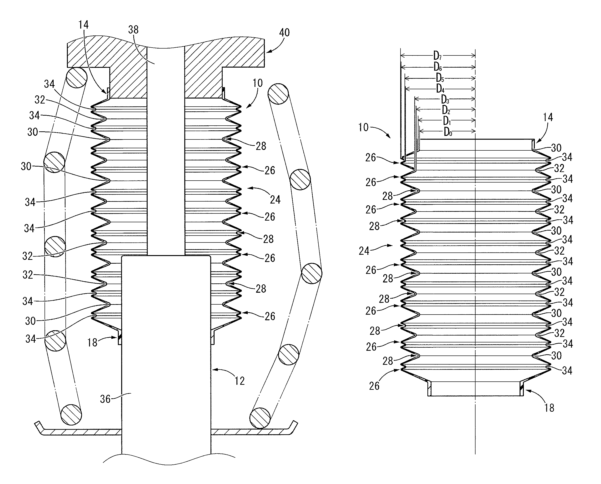
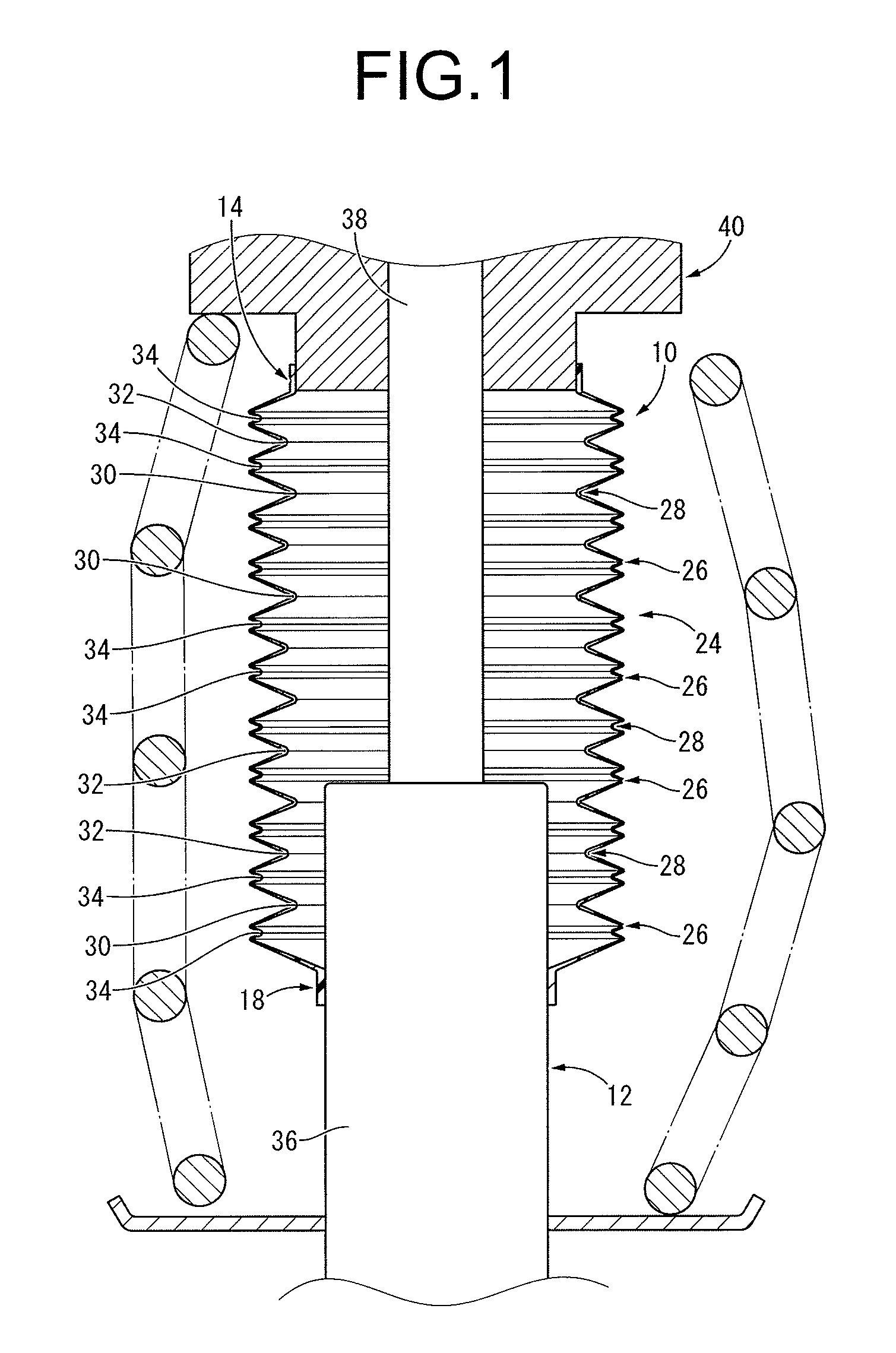
[0033]Referring to FIG. 1, there is depicted a dust cover 10 as a first embodiment of the protective cover constructed according to the present invention, in a state of being mounted onto a shock absorber 12 of a suspension mechanism. In the description hereinbelow, as a general rule the vertical direction refers to the vertical direction in FIG. 1, which is also the axial direction of the dust cover 10.

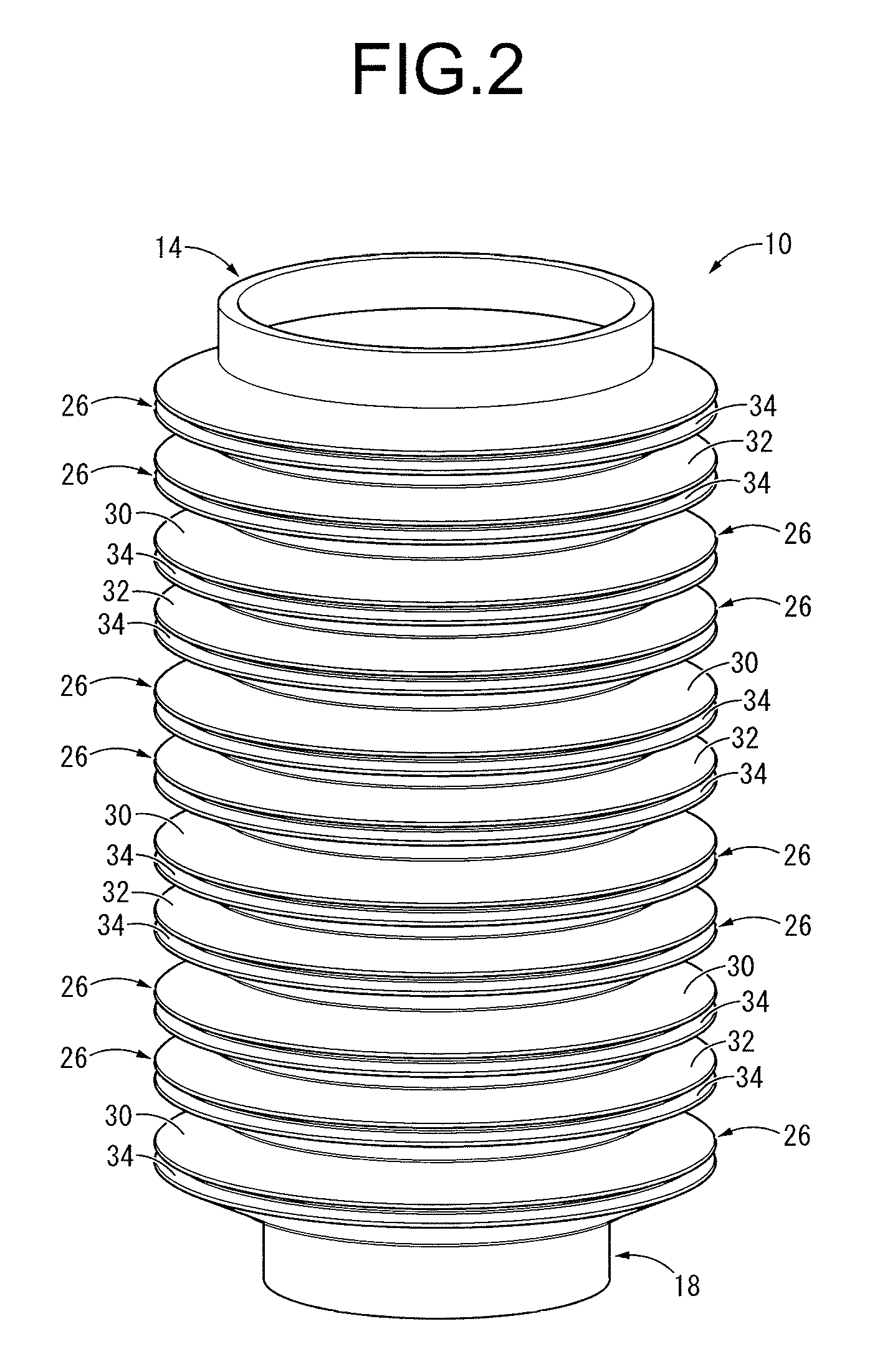
[0034]Described more specifically, as depicted in FIGS. 2 through 5, the dust cover 10 has a thin-walled, generally round tubular shape overall, and is endowed with elasticity by being made of a rubber elastic body, synthetic resin, or the like. While no particular limitation is imposed as to the rubber elastic body or synthetic resin that forms the dust cover 10, in the present embodiment, for example, a material made from polypropylene (PP) serving as a thermoplastic resin mixed with e...


PUM

PropertyMeasurementUnit
diameteraaaaaaaaaa
thickness dimensionaaaaaaaaaa
thermoplasticaaaaaaaaaa

Abstract

A protective cover including a bellows portion wherein a plurality of valleys and peaks are arranged alternately. The valleys include a plurality of large valleys and a plurality of intermediate valleys whose inside and outside diameter dimensions at bottoms are greater than those of the large valleys, and the large valleys and the intermediate valleys are arranged alternately. Small valleys whose inside and outside diameter dimensions at bottoms are greater than those of the intermediate valleys are respectively arranged between the large valleys and the intermediate valleys. The peaks are respectively arranged between the large valleys and the small valleys as well as between the intermediate valleys and the small valleys, and apexes of the peaks have a same outside diameter dimension as one another. The apexes of the peaks are made thinner than the bottoms of the large valleys.

Description

INCORPORATED BY REFERENCE[0001]This is a Continuation of International Application No. PCT / JP2011 / 006366 filed on Nov. 15, 2011, the disclosure of which including the specification, drawings and abstract is incorporated herein by reference in its entirety.BACKGROUND OF THE INVENTION[0002]1. Field of the Invention[0003]The present invention relates generally to a protective cover adapted to be externally fitted onto components such as shock absorbers of automotive suspensions, robot arms, or the like, which are to be permitted extension / contraction or bend, and prevent adhesion of water, dust, or other foreign matters to the components. The present invention also relates to a manufacturing method of the same.[0004]2. Description of the Related Art[0005]Conventionally, tubular protective covers (dust covers) are generally externally fitted onto shock absorbers of automotive suspensions, robot arms, or the like serving as components to be attached, in order to permit extension / contract...

Claims


Application Information

Patent Timeline
Patent Type & Authority Patents(United States)
IPC IPC(8): F16J3/00F16F9/38F16J15/52F16J3/04B29C49/04B29L22/02B29L31/00
CPCF16J15/52F16F9/38F16J3/041F16J3/043B29C49/04B29L2022/025B29L2031/755
Inventor MATSUMURA, HIROYUKINAKAMURA, YORIKAZU
Owner SUMITOMO RIKO CO LTD
Why Eureka
Try Eureka