
Rotor shaft

a technology of rotating shafts and shafts, applied in the direction of rod connections, magnetic circuit rotating parts, magnetic circuit shapes/forms/construction, etc., can solve the problems of press-fit load and large annular projection diameter, and achieve the effect of large fitting strength

Inactive Publication Date: 2006-02-14
HONDA MOTOR CO LTD
View PDF3 Cites 9 Cited by
  • Summary
  • Abstract
  • Description
  • Claims
  • Application Information

AI Technical Summary

Benefits of technology

The present invention provides a rotor shaft with multiple separately formed component parts that can fit together with sufficient strength during operation. The component parts have annular projections on their facing surfaces that fit tightly together to ensure a large axial load can act upon the abutting surfaces. The annular projections have a substantially equal thickness and can expand and contract with changes in temperature and centrifugal force during operation to maintain a tight contact. This design reduces the rigidity of the rotor shaft and increases the axial load acting upon the abutting surfaces, resulting in a more stable rotation center.

Problems solved by technology

Further, the provision of the annular projections in an outer peripheral portion of the end surfaces of the rotor shaft component parts can result in a larger diameter of the annular projections.
Further, the annular projections having a substantially small thickness (or radial dimension) can lower the rigidity thereof and thus reduce the press-fit load, whereby increasing the axial load acting upon the abutting surfaces of the fitting portions of the rotor shaft component parts.

Method used


Image

  • Rotor shaft
  • Rotor shaft
  • Rotor shaft

Examples


Embodiment Construction

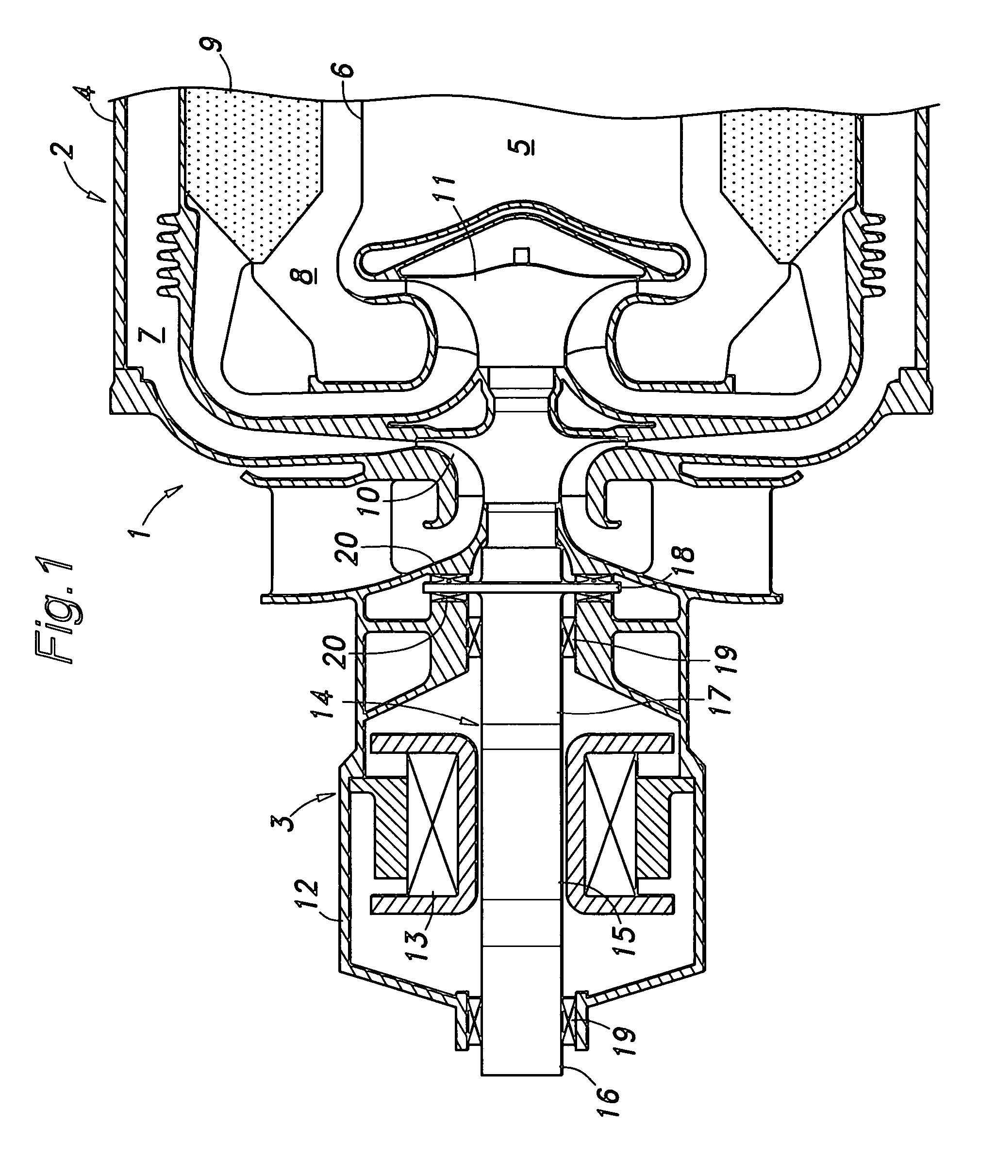
[0015]FIG. 1 is a cross-sectional view showing a structure of a gas turbine generator to which the present invention is applied. This gas turbine engine 1 comprises an engine portion 2 for generating a driving force, and an electric generator portion 3 rotationally driven by the engine portion 2.

[0016]The engine portion 2 has an outer housing 4 of which end away from the generator portion 3 is substantially closed, and an inner housing 6 concentrically received in the outer housing 4 to define a combustion chamber 5. Between the outer housing 4 and the inner housing 6 are provided an air intake passage 7, a combustion gas passage 8, and a heat exchanger 9.

[0017]The engine portion 2 further comprises a compressor wheel 10 for taking in and compressing outer air, and a turbine wheel 11 rotationally driven by the flow of combustion gas, where the compressor wheel 10 and the turbine wheel 11 are provided concentrically with each other. Although not shown in the drawing, diffusers, stato...


PUM


Abstract

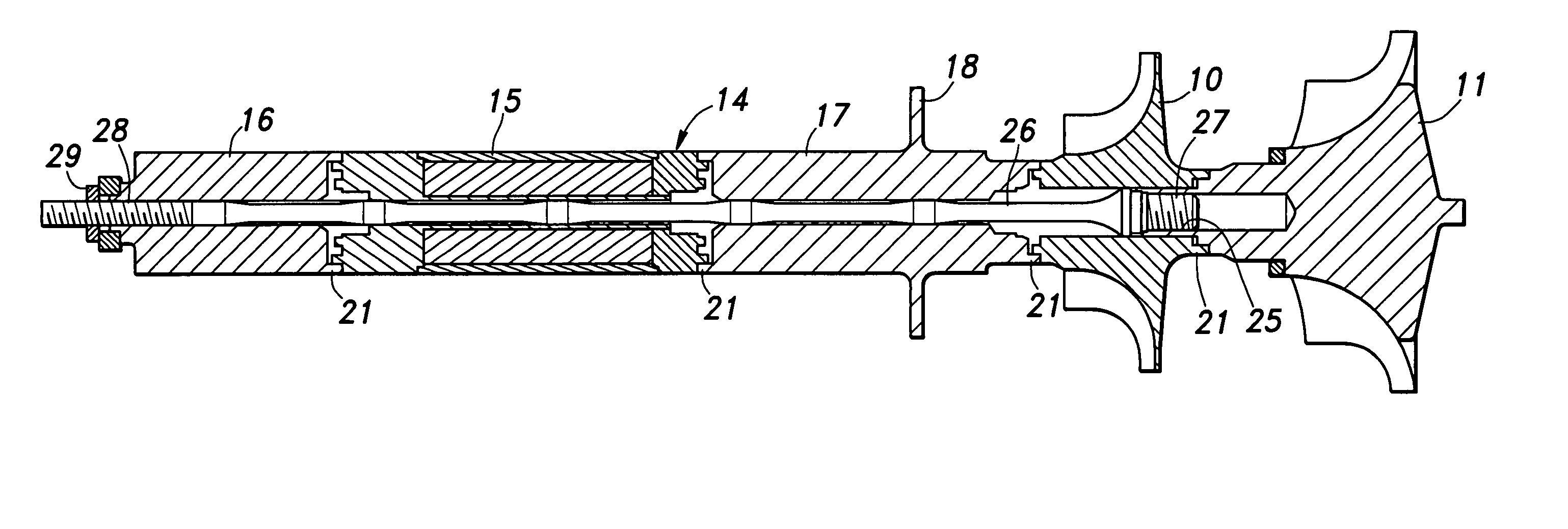
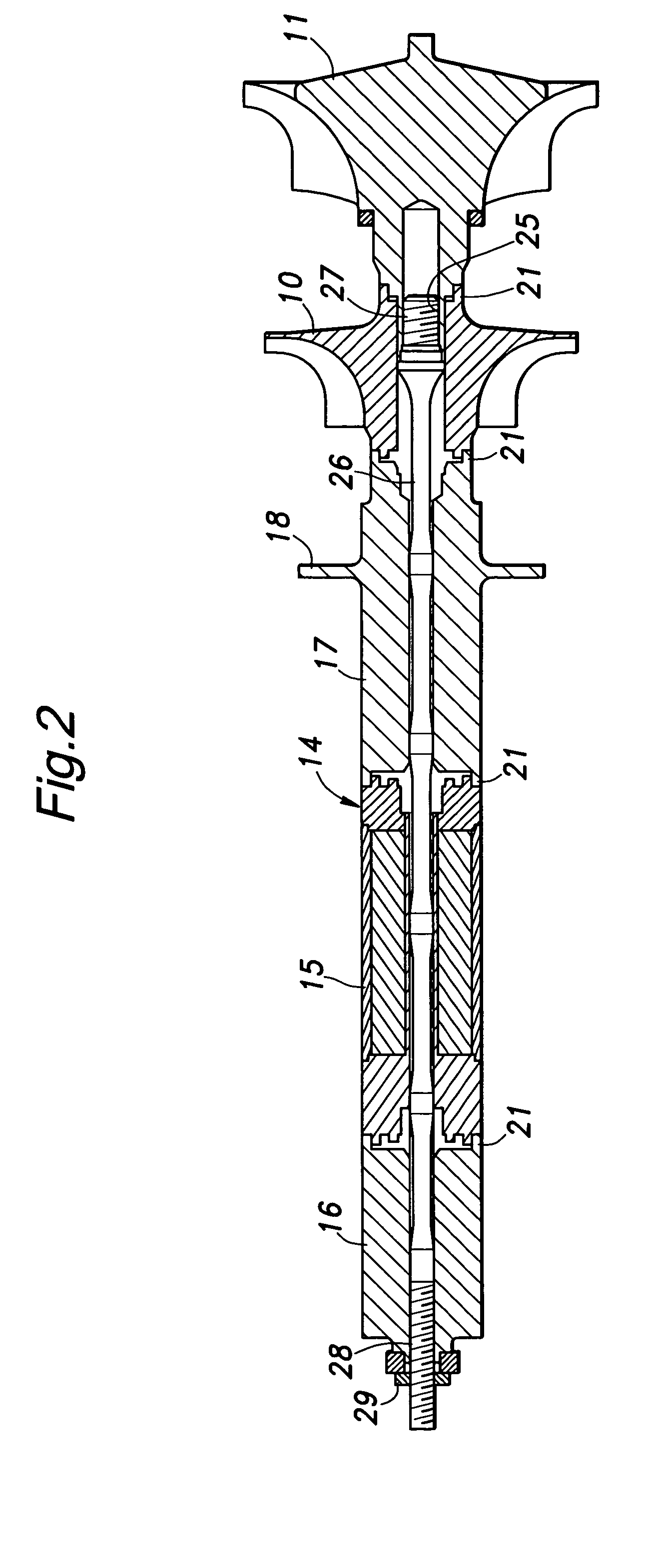
The present invention provides a rotor shaft, comprising: a rod member (26); and a plurality of separately formed component parts (such as a compressor wheel 10, a turbine wheel 11 and a rotor 14 of an electric generator) through which the rod member extends so that the plurality of component parts are joined together on an axis of the rod member, wherein mutually facing axial end surfaces of adjoining ones of the plurality of component parts are formed with annular projections (22, 23) having a substantially same radial dimension (or thickness) such that an outer circumferential surface of the annular projection of one component part can tightly contact an inner circumferential surface of the annular projection of an adjoining component part.

Description

TECHNICAL FIELD[0001]The present invention relates to a rotor shaft. More specifically, the present invention relates to a rotor shaft, such as a main shaft of an electric generator driven by a gas turbine engine, comprising a plurality of separately made component parts which are joined together on an axis of a rod member passing through the plurality of component parts.BACKGROUND OF THE INVENTION[0002]A main shaft of an electric generator driven by a gas turbine engine generally comprises a plurality of individually formed component parts such as a compressor wheel, a turbine wheel, a support structure for permanent magnets, a plurality of journals, thrust plates, etc., and these component parts are joined together on a common axis. Conventionally, the joint of the component parts is typically achieved by passing a single rod member through the component parts to be joined together, and then applying an axial load upon abutting surfaces of the component parts on the rod member by ...

Claims


Application Information

Patent Timeline
Patent Type & Authority Patents(United States)
IPC IPC(8): H02K7/18F01D5/02F01D25/00F02B39/00F16C3/02F16D1/02F16D1/06F16D1/09H02K7/00
CPCF01D5/026F16C3/02F16D1/02H02K7/003Y10T403/5706F05D2230/64F05D2260/30Y10T403/55F16C2360/23F16C2380/26
Inventor ISHII, ICHIRO
Owner HONDA MOTOR CO LTD
Learn More