Lifter

a lifter and body technology, applied in the field of lifters, can solve the problems of limiting the freedom of design of the lifter to a large degree, and the inner wall of the cylinder can slide wear, so as to reduce the cocking due to the inclination of the lifter body, reduce the cocking, and reduce the cocking

Inactive Publication Date: 2017-02-23
OTICS CORP
View PDF0 Cites 2 Cited by
  • Summary
  • Abstract
  • Description
  • Claims
  • Application Information

AI Technical Summary

Benefits of technology

[0009]Therefore, an object of the invention is to provide a lifter which has a high degree in the freedom of design and can reduce cocking.
[0010]According to one embodiment of the invention, a lifter includes a roller caused to abut against a cam thereby to be pressed and a lifter body rotatably supporting the roller and housed in a guide hole of a lifter guide so as to be reciprocable in the guide hole. The lifter body includes a cylindrical part having an outer periphery formed into a cylindrical shape such that the outer periphery is slidable on an inner periphery of the guide hole. The cylindrical part has one of two axial ends, the one axial end being formed with a skirt covering the roller. The cylindrical part also includes a rotation stopper formed to protrude outward from the other axial end of the cylindrical part, the other axial end being located opposite a side where the skirt is located. The rotation stopper prevents the lifter body from being rotated about an axis thereof relative to the lifter guide.
[0011]An axial dimension of the cylindrical part can be rendered larger since the cylindrical part of the lifter body has the skirt covering the roller. This can ensure a sufficiently large axial region in which the outer periphery of the cylindrical part slides on the inner periphery of the guide hole, with the result that the inclination of the lifter body in the guide hole can be reduced. Consequently, cocking due to inclination of the lifter body can be reduced.
[0012]Furthermore, the rotation stopper is formed to protrude outward from the other axial end of the cylindrical part, which other axial end is located opposite a side where the skirt is located. Thus, the rotation stopper is disposed at the position sufficiently deviated from the rotation trajectory of the cam. This resolves concern with the interference of the rotation stopper with the cam and accordingly improves the freedom in the design of the rotation stopper and its periphery. Moreover, since the rotation stopper is located at the other axial end of the cylindrical part but not at an axial middle of the cylindrical part, the lifter body can be ground by a centerless processing or the like while being rotated.

Problems solved by technology

As a result, there would be a possibility of sliding wear of the inner wall of the cylinder in addition to occurrence of noise.
This limits the freedom in the design of the lifter to a large degree.

Method used


Image

  • Lifter
  • Lifter
  • Lifter

Examples


Embodiment Construction

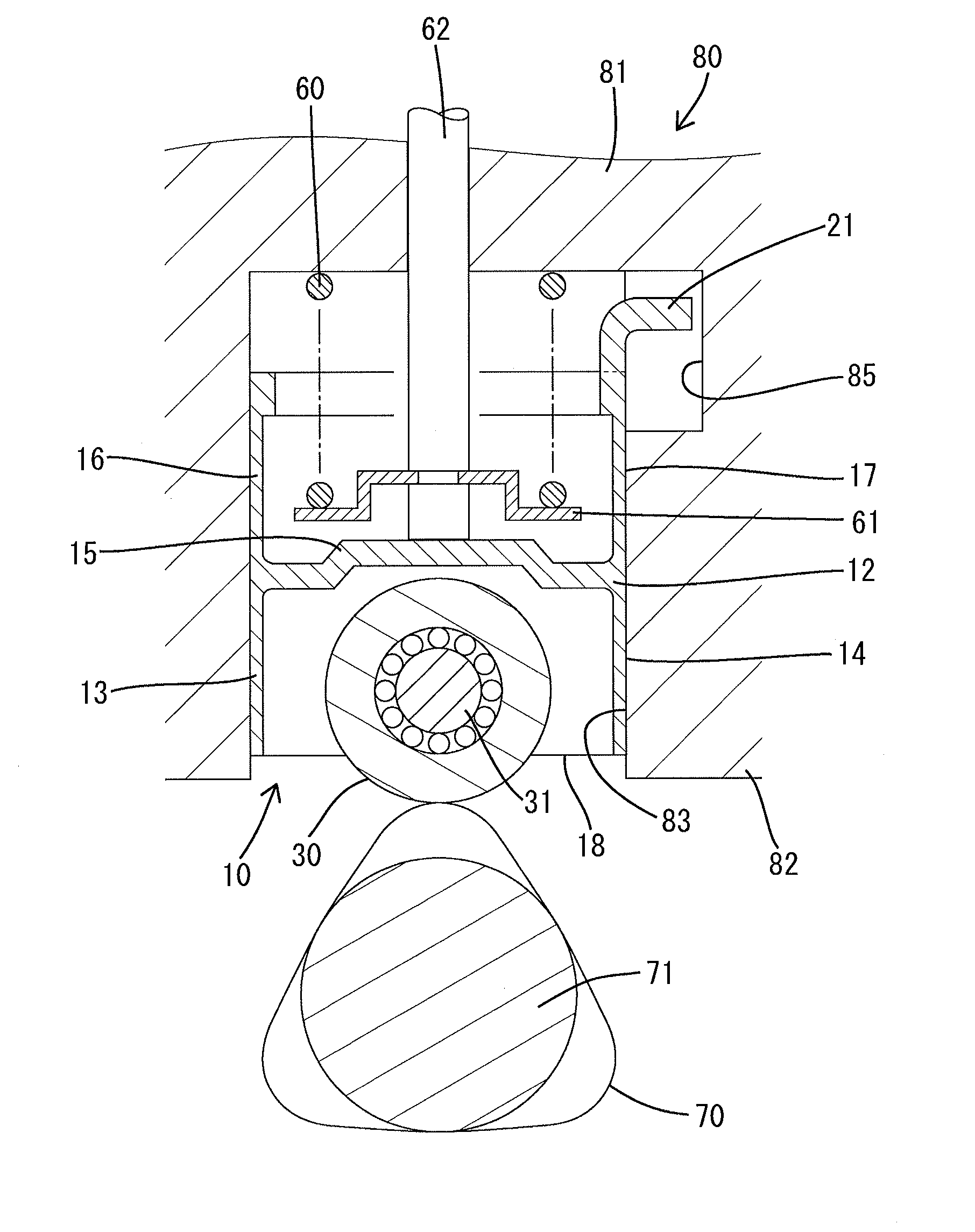
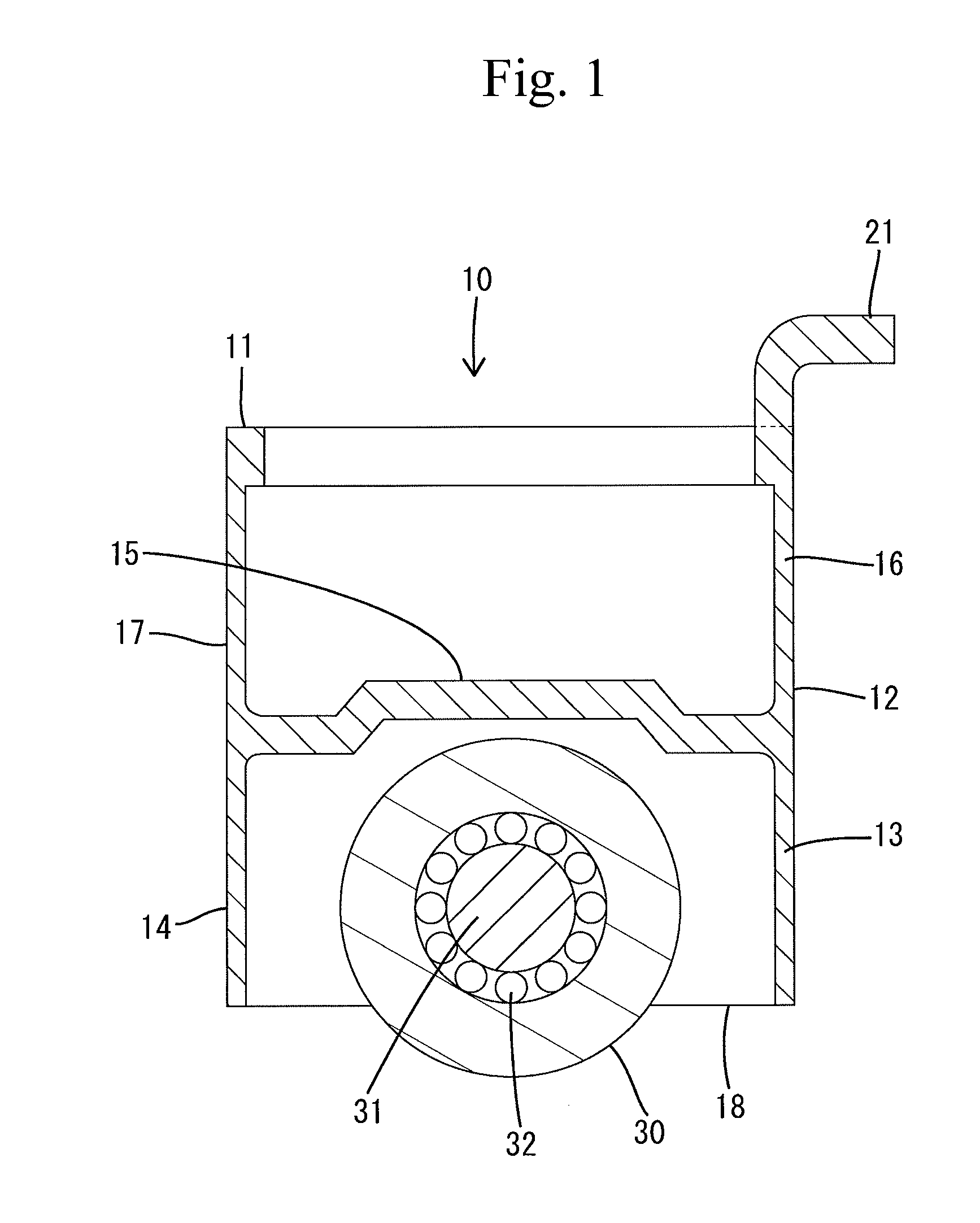
[0016]An embodiment of the present invention will be described with reference to the drawings. A lifter 10 according to the embodiment is a pump lifter mounted on a fuel supply system 80 of an internal combustion engine.

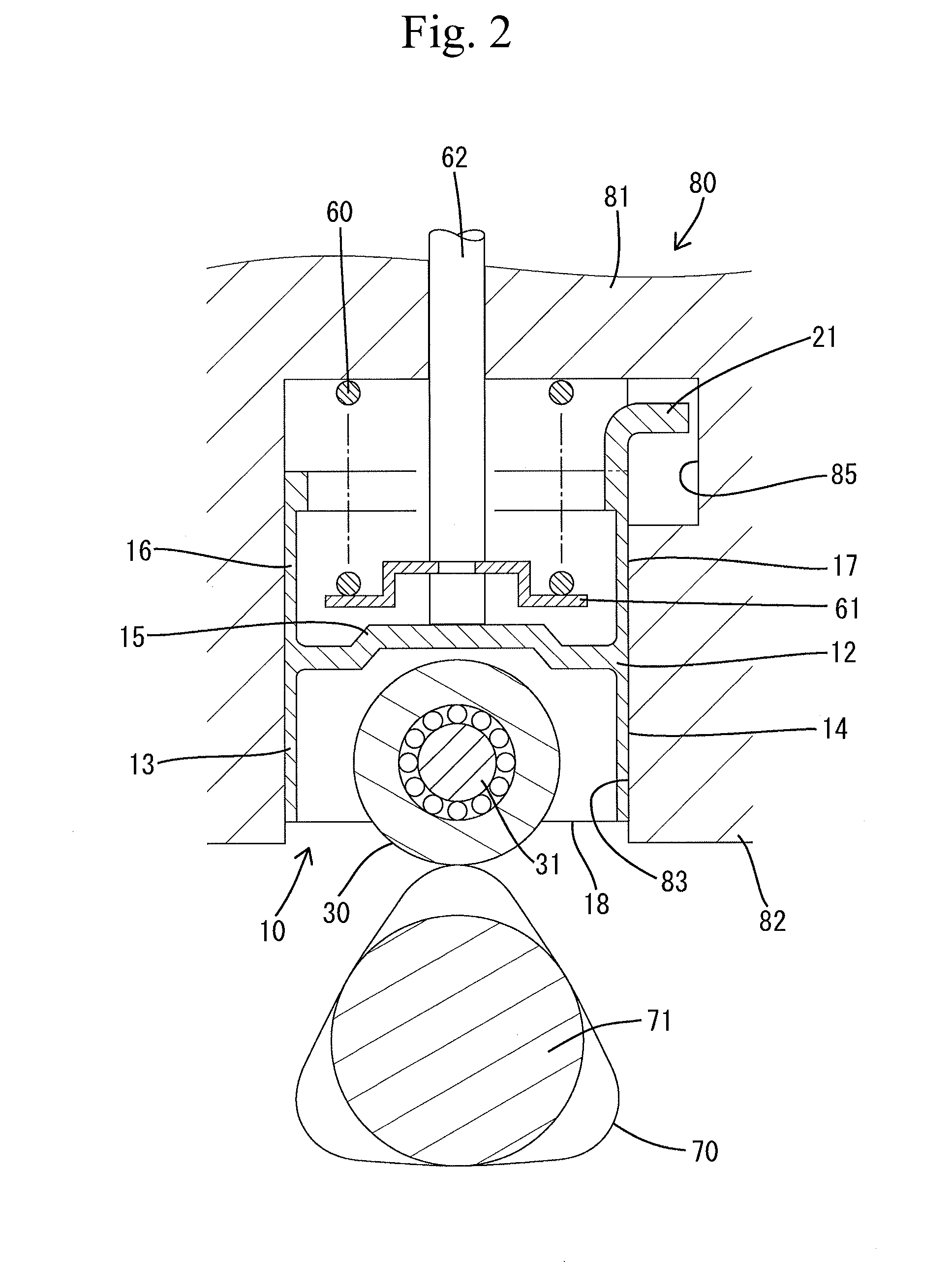
[0017]Referring to FIG. 2, the fuel supply system 80 includes, in addition to the lifter 10, a compression coil spring 60 biasing a roller 30 of the lifter 10 in a direction such that the roller 30 is pressed against a cam 70, a retainer 61 cooperative with an upwardly located cylinder 81 to retain the compression coil spring 60 therebetween, a plunger 62 housed in the cylinder 81 so as to be reciprocable, and a pump chamber (not shown) defined by the cylinder 81 and the plunger 62. The roller 30 will be described in detail later. The fuel supply system 80 includes a downwardly located cylinder which will be referred to as “a lifter guide 82” and is formed with a guide hole 83 extending in an axial direction or up-down direction as viewed in FIG. 2. The lifter 10 is ...


PUM


Abstract

A lifter includes a roller caused to abut against a cam thereby to be pressed and a lifter body rotatably supporting the roller and housed in a guide hole of a lifter guide so as to be reciprocable in the guide hole. The lifter body includes a cylindrical part and a rotation stopper. The cylindrical part has an outer periphery formed into a cylindrical shape such that the outer periphery is slidable on an inner periphery of the guide hole. The cylindrical part has one of two axial ends, the one end being formed with a skirt covering the roller. The rotation stopper is formed to protrude outward from the other axial end of the cylindrical part, the other axial end being located opposite a side where the skirt is located. The rotation stopper prevents the lifter body from being rotated about an axis thereof relative to the lifter guide.

Description

CROSS-REFERENCE TO RELATED APPLICATIONS[0001]This application is based upon and claims the benefit of priority from the prior Japanese Patent Application No. 2015-161571 filed on Aug. 19, 2015, the entire contents of which are incorporated herein by reference.BACKGROUND[0002]1. Technical Field[0003]The present invention relates to a lifter.[0004]2. Related Art[0005]Japanese Patent Application Publication No. JP-A-2012-2115 discloses a lifter which is a roller lifter for use with internal combustion engines such as automobile engines. The disclosed lifter includes a lifter body and a roller which is caused to abut against an outer periphery of a cam thereby to be pressed. The lifter body includes a cylindrical part having an outer periphery slidable on an inner wall of a cylinder and a pair of supports axially protruding from one axial end of the cylindrical part. The roller is rotatably mounted on a support pin extending through both supports.[0006]The cylindrical part has a rotatio...

Claims


Application Information

Patent Timeline
Patent Type & Authority Applications(United States)
IPC IPC(8): F01L1/14
CPCF01L1/14F01L2107/00F01L2105/02F01L1/16F02M59/102F01L2307/00F01L1/143F01L1/146F01L2303/00F01L2305/00F01L2305/02
Inventor TODO, KIMIHIKOMIYAZAWA, DAIKISASAKI, TATSUYA
Owner OTICS CORP
Why Eureka
Try Eureka