Bearing apparatus, spindle motor, and disk drive apparatus

a technology of bearing apparatus and disk drive, which is applied in the direction of sliding contact bearings, maintaining head carrier alignment, instruments, etc., can solve the problems of limiting and not obtaining sufficient supporting force between the shaft and the sleeve, so as to limit the axial dimension of the bearing apparatus and achieve sufficient axial dimension

Inactive Publication Date: 2012-10-02
NIDEC CORP
View PDF46 Cites 28 Cited by
  • Summary
  • Abstract
  • Description
  • Claims
  • Application Information

AI Technical Summary

Benefits of technology

[0009]According to this preferred embodiment of the present invention, it is possible to limit the axial dimension of the bearing apparatus as a whole while also enabling both the radial dynamic pressure groove array and the pumping groove array to have a sufficient axial dimension. In addition, it is possible to cause any air bubbles introduced into the lubricating oil by the pumping groove array to be sent into the through hole efficiently, so that the air bubbles are discharged out of the bearing apparatus through the lower surface of the lubricating oil.

Problems solved by technology

The bearing apparatus having such a structure has a problem in that, when it is desirable to limit the axial dimension of the bearing apparatus, both the axial dimension of the radial dynamic pressure bearing portion and that of the pumping action portion is not sufficient enough to allow both the radial dynamic pressure bearing portion and the pumping action portion to both exhibit a sufficient performance.
If the air bubbles introduced into the lubricating fluid are accumulated in the vicinity of a thrust dynamic pressure bearing portion or the radial dynamic pressure bearing portion, generation of a dynamic pressure in the lubricating fluid may be hindered.
If this happens, a sufficient supporting force may not be obtained between the shaft and the sleeve to allow the bearing apparatus to maintain a sufficient rotation performance.

Method used


Image

  • Bearing apparatus, spindle motor, and disk drive apparatus
  • Bearing apparatus, spindle motor, and disk drive apparatus
  • Bearing apparatus, spindle motor, and disk drive apparatus

Examples


Embodiment Construction

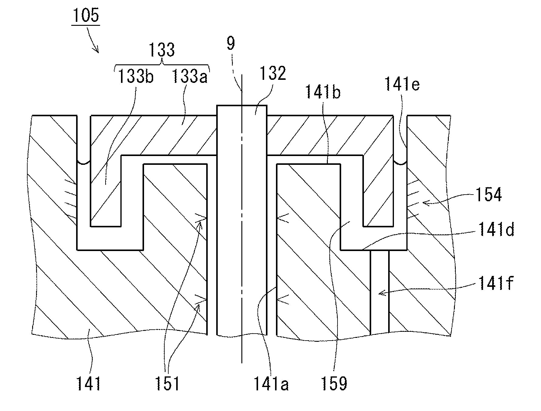
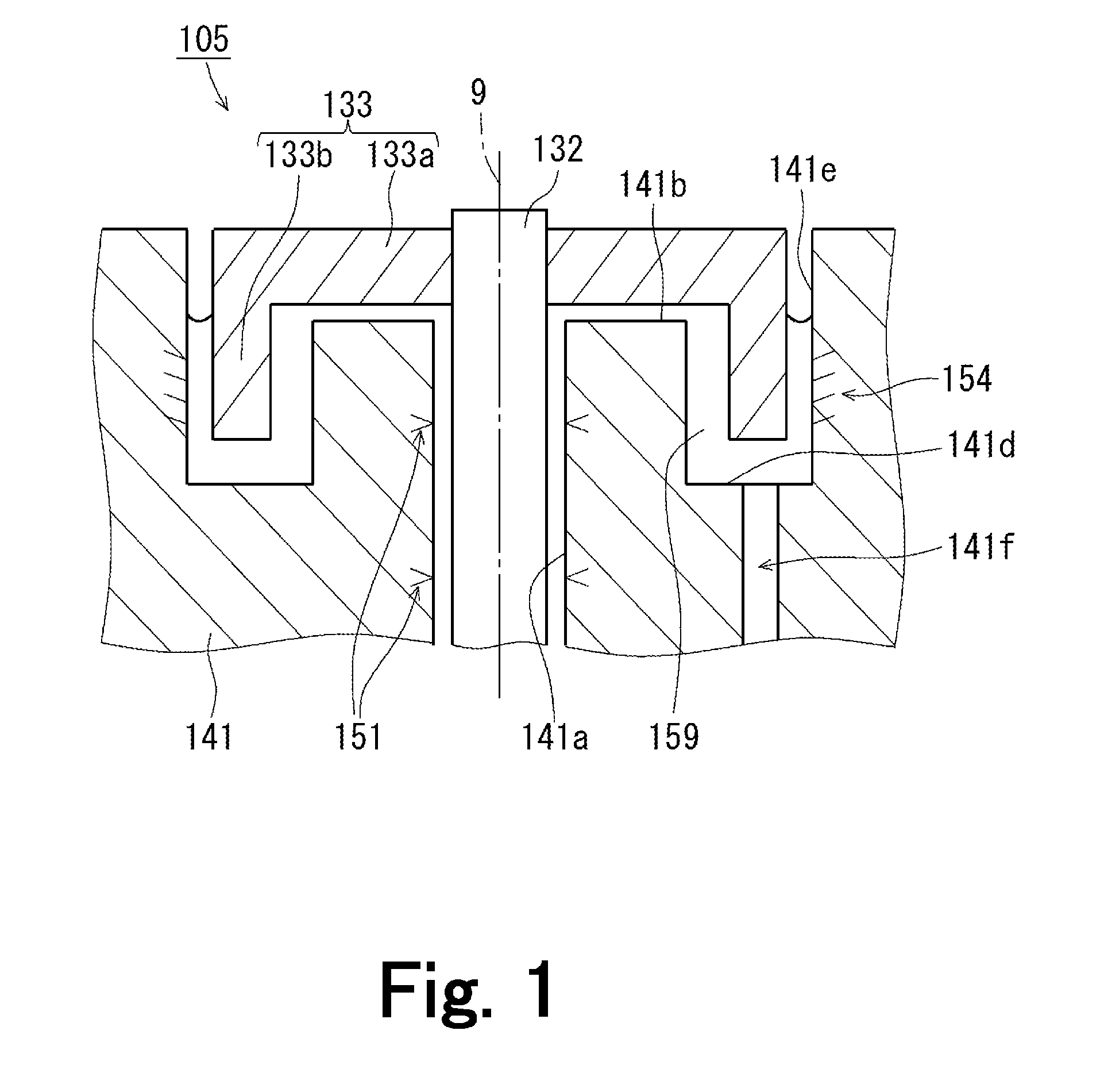
[0019]Hereinafter, preferred embodiments of the present invention will be described with reference to the accompanying drawings. It is assumed herein that an upward / downward direction (i.e., a vertical direction) is defined along a center axis 9, with a direction in which a cylindrical portion 133b of a first cup portion 133 projects defined as a downward direction. The shape of each member and relative positions of different members will be described based on this assumption. It should be noted, however, that the above definition of the upward / downward direction is simply applied to facilitate the description provided herein, and should not be construed to restrict in any way the orientation of a bearing apparatus, a spindle motor, or a disk drive apparatus according to any preferred embodiment of the present invention when actually installed in a device.

[0020]FIG. 1 is a diagram illustrating the structure of a bearing apparatus 105 according to a preferred embodiment of the presen...


PUM


Abstract

In a bearing apparatus, a first cup portion defining a portion of a stationary portion of a bearing apparatus includes a circular plate portion and a cylindrical portion projecting downward from an outer edge portion of the circular plate portion. A rotating portion of the bearing apparatus includes an annular recessed portion arranged to accommodate at least a lower end portion of the cylindrical portion. Accordingly, it is possible to limit the axial dimension of the bearing apparatus while also enabling both a radial dynamic pressure groove array and a pumping groove array to have a sufficient axial dimension. Additionally, one end of a through hole defined in the rotating portion is arranged to open into the annular recessed portion, so that any air bubbles introduced into a lubricating oil by the pumping groove array can be efficiently caused to flow downward through the through hole and out of the bearing apparatus.

Description

BACKGROUND OF THE INVENTION[0001]1. Field of the Invention[0002]The present invention relates to a bearing apparatus, a spindle motor, and a disk drive apparatus.[0003]2. Description of the Related Art[0004]Hard disk apparatuses and optical disk apparatuses are typically provided with a spindle motor arranged to rotate a disk or disks about a center axis thereof. The spindle motor includes a stationary portion fixed to a housing of the disk drive apparatus, and a rotating portion arranged to rotate while supporting the disk(s). The spindle motor is arranged to produce a torque centered on the center axis by magnetic flux generated between the stationary and rotating portions, whereby the rotating portion is caused to rotate with respect to the stationary portion.[0005]The stationary and rotating portions of the spindle motor are joined to each other through a bearing apparatus. In recent years, in particular, spindle motors have often been provided with a bearing apparatus in which ...

Claims


Application Information

Patent Timeline
Patent Type & Authority Patents(United States)
IPC IPC(8): F16C32/06
CPCF16C17/10F16C33/107F16C33/745G11B19/2036H02K7/08G11B19/2009H02K7/085F16C32/0659H02K5/1675F16C2370/12F16C17/107
Inventor KIMURA, AKIHIROHIRONO, TEIICHISAKURADA, KUNIOHORISE, KYOKO
Owner NIDEC CORP
Why Eureka
Try Eureka