Device for extracting cutting bit from holder
- Summary
- Abstract
- Description
- Claims
- Application Information
AI Technical Summary
Benefits of technology
Problems solved by technology
Method used
Image
Examples
Embodiment Construction
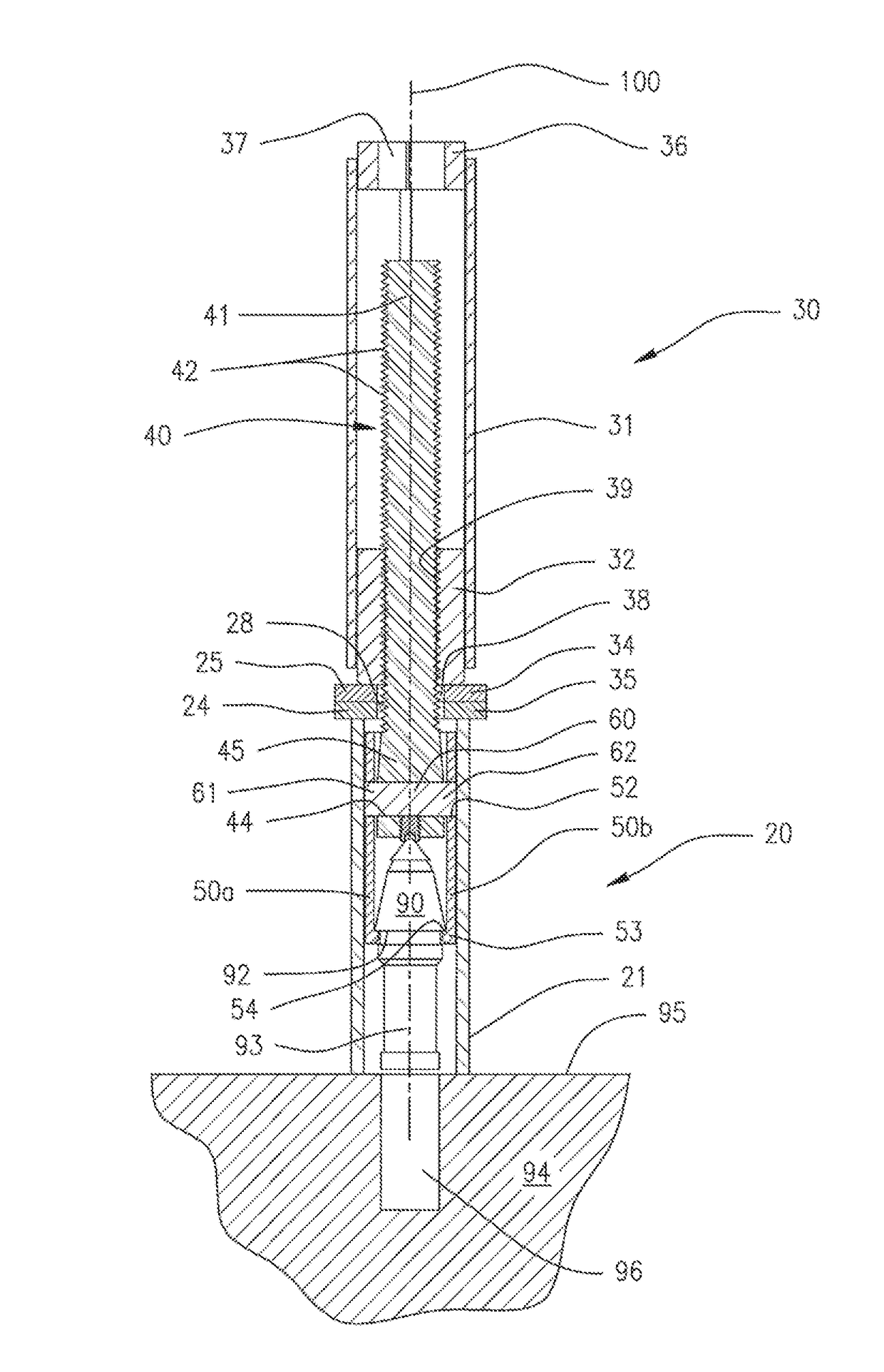
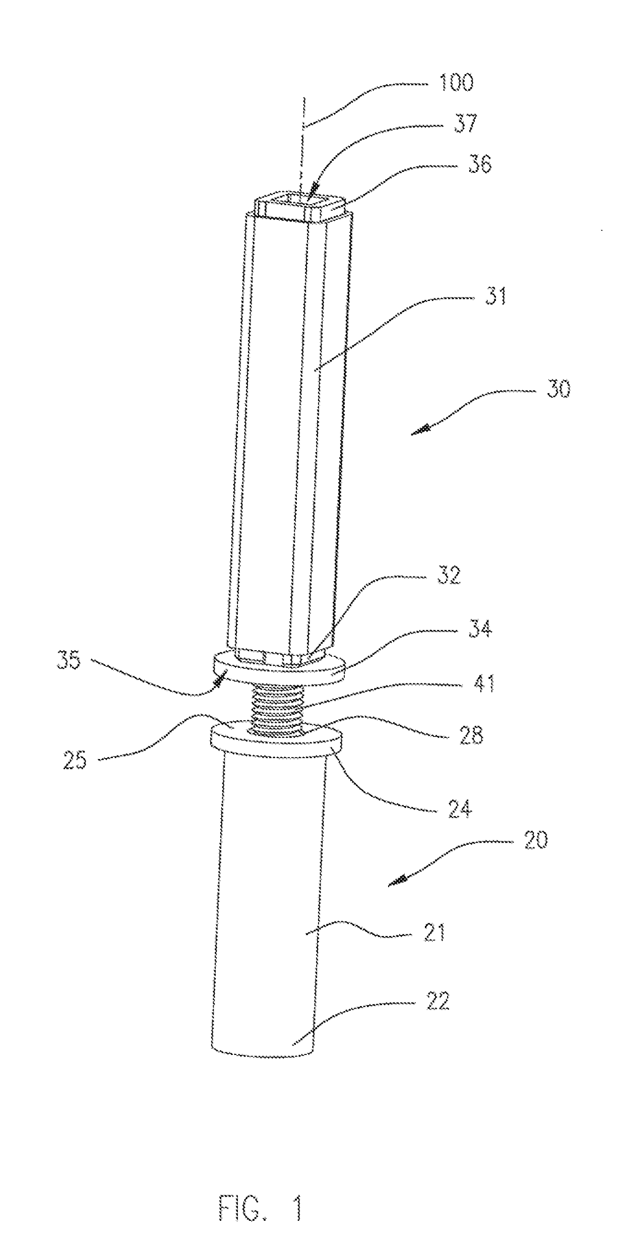
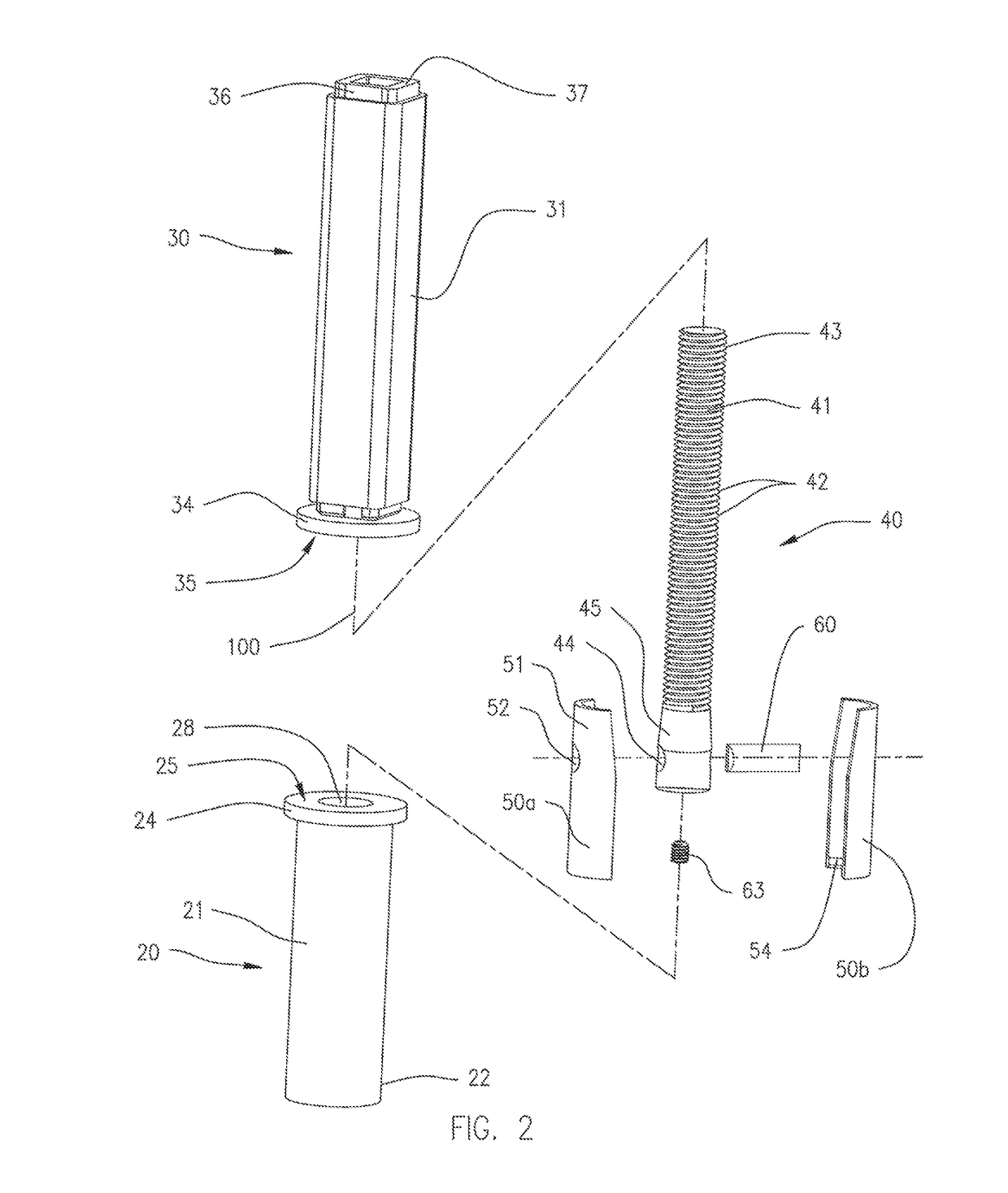
[0031]A tool 10 for separating a cutting bit 90 from an auger 94 is shown in FIGS. 1-3. An auger 94 including cutting bits 90 is shown in FIG. 7. The cutting bit 90 (FIG. 3) has a base end 93 that is inserted into a retaining hole 96 of a cutting bit holder or cutting equipment, illustrated as an auger 94, and an upper end protruding above a surface 95 of a portion of the auger 94. Cutting bits 90 and the auger 94 are known in the prior art. These cutting bits 90 are typically provided with engagement surfaces, such as an annular peripheral groove 92, that provides control surfaces on the cutting bit 90 to facilitate attachment of a gripping element, illustrated as bit jaws 50, for removal of the cutting bit 90 from the auger 94. The bit jaws 50 include an in-turned ledge 54 for engaging and securing into the annular peripheral groove 92 from opposite sides of the cutting bit 90. The in-turned ledge has an arcuate that follows the outer curvature of the wail of the bit jaw 50. The i...
PUM
| Property | Measurement | Unit |
|---|---|---|
| Fraction | aaaaa | aaaaa |
| Fraction | aaaaa | aaaaa |
| Fraction | aaaaa | aaaaa |
Abstract
Description
Claims
Application Information
 - R&D
- Intellectual Property
- Life Sciences
- Materials
- Tech Scout
- Unparalleled Data Quality
- Higher Quality Content
- 60% Fewer Hallucinations
Browse by: Latest US Patents, China's latest patents, Technical Efficacy Thesaurus, Application Domain, Technology Topic, Popular Technical Reports.
© 2025 PatSnap. All rights reserved.Legal|Privacy policy|Modern Slavery Act Transparency Statement|Sitemap|About US| Contact US: help@patsnap.com


