Seat driving device

a driving device and seat technology, applied in the direction of movable seats, vehicle components, vehicle arrangements, etc., can solve the problems of seat not being able to carry an occupant, seat back cannot be returned to the use state, seat back cannot be adjusted to a desired position, etc., to achieve the effect of suppressing motor operation noise, speeding up the tilting operation of the seat back, and improving seat performan

Active Publication Date: 2019-11-26
MITSUBA CORP +1
View PDF18 Cites 1 Cited by
  • Summary
  • Abstract
  • Description
  • Claims
  • Application Information

AI Technical Summary

Benefits of technology

[0008]In the present invention, the multi-thread worm is used in the speed reduction mechanism of the seat driving device, so that it is possible to speed up the tilting operation of the seat back without changing the motor rotation speed. Thus, performance of the seat can be improved while suppressing motor operation noise. Further, the moving time of the seat back can be shortened, allowing temporal stress on a user to be alleviated. Further, adopting the multi-thread worm facilitates rotation of the worm from the worm wheel side, which in turn facilitates manual reverse operation in emergency. This allows the manual reverse operation to be performed from outside the seat driving device, and hence, the state of the seat back can be manually changed even in emergency. Thus, even when the motor fails to operate, the seat back can still be moved to a desired position. Further, even when a failure occurs in a state where the seat back is at the storage position, the seat can be returned to the use state.

Problems solved by technology

However, in a conventional electric seat, when an electric motor for drive dose not work due to failure or the like, the seat back is fixed at that position, which may prevent the seat back from being adjusted to a desired position.
Particularly, when a failure occurs in a state where the seat back is at the storage position, the seat cannot be returned to the use state, that is, the seat cannot carry an occupant.
Therefore, when the shaft directly coupled to the motor is attempted to be rotated, the worm or worm wheel of the speed reduction mechanism part may be damaged.
Thus, it is difficult to externally manually return the seat back to the use position, so that seat reclining operation is difficult to perform during abnormality.
Further, when the seat back is to be displaced between the use position and the storage position, if a motor is driven to move the seat back, it takes some time.

Method used


Image

  • Seat driving device
  • Seat driving device
  • Seat driving device

Examples


Embodiment Construction

[0014]Hereinafter, an embodiment of the present invention will be described in detail based on the drawings. An object of the present embodiment is to provide a seat driving device capable of manually performing angle adjustment operation of a seat back without damaging a motor even at failure. Another object of the present embodiment is to quickly move the seat back to the storage position to alleviate temporal stress on a user.

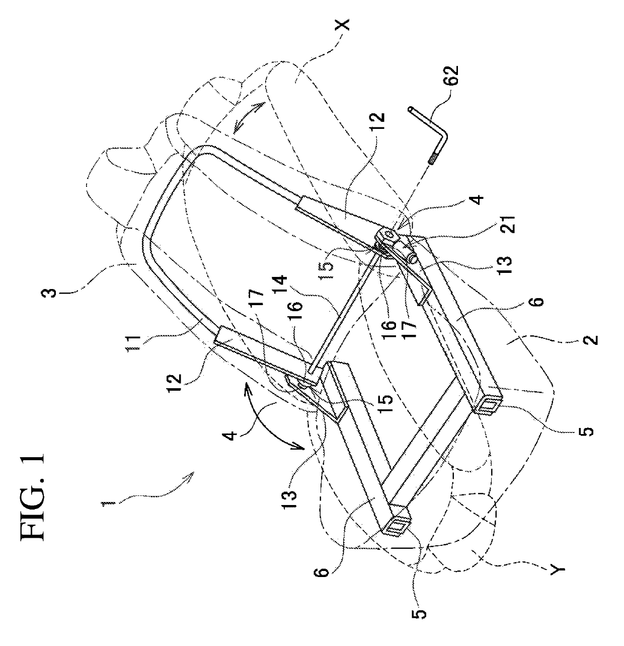
[0015]FIG. 1 is an explanatory view illustrating the configuration of a vehicle seat using a seat driving device according to the embodiment of the present invention. As illustrated in FIG. 1, a seat 1 is constituted of a seat cushion 2 and a seat back 3 and is mounted on a vehicle such as a car. A reclining mechanism 4 is provided between the seat cushion 2 and the seat back 3. In the seat 1, the reclining mechanism 4 that can appropriately adjust the tilt angle of the seat back 3 has a seat driving device 21 using an electric motor. That is, the seat 1 is ...


PUM


Abstract

A seat 1 has a seat cushion 2 and a seat back 3 and is mounted on a vehicle such as a car. A reclining mechanism 4 capable of adjusting the tilt angle of the seat back 3 is provided between the seat cushion 2 and the seat back 3. The reclining mechanism 4 has a seat driving device 21 provided with an electric motor 22 and a speed reduction mechanism 23. The speed reduction mechanism 23 has a worm shaft 45 connected to a motor shaft 34 of the motor 22 and a worm wheel 47 meshed with a worm 46 of the worm shaft 45. The worm 46 is a multi-thread worm having two or more threads.

Description

BACKGROUND OF THE INVENTIONField of the Invention[0001]The present invention relates to a vehicle seat driving device and, more particularly, to an electric seat driving device that performs tilting operation of a seat back.Related Art Statement[0002]As a vehicle seat such as a car seat, there is known one provided with a seat tilting mechanism that adjusts the reclining angle of a seat back and moves the seat back between a use position and a storage position. Conventionally, such a seat tilting mechanism is generally manually operated; however, in recent years, the number of vehicles mounted with a seat whose tilting operation is electrically performed is increasing mainly in luxurious cars. JP 09-109750 A describes a vehicle seat in which reclining operation of the seat back is electrically performed by an electric motor. In the disclosed technology, the reclining angle of the seat back is adjusted by a seat back adjuster operated by a reclining motor.[0003]In the electric seat a...

Claims


Application Information

Patent Timeline
Patent Type & Authority Patents(United States)
IPC IPC(8): B60N2/02B60N2/22
CPCB60N2/0232B60N2/2231B60N2002/0236B60N2/02253B60N2/02246
Inventor IWATATE, NAOHIROBUSUJIMA, JUNICHIKATSUBE, KENICHINAKAMURA, TAKESHI
Owner MITSUBA CORP
Why Eureka
Try Eureka