Modular parallel technique for resonant converter

a resonant converter and module parallel technology, applied in the direction of electric variable regulation, process and machine control, instruments, etc., can solve the problems of parallel power supply, higher cost of interleaved, and additional gate-drive circuits, so as to achieve no additional cost, no additional control, and no additional cost

Active Publication Date: 2019-11-26
MURATA MFG CO LTD
View PDF25 Cites 9 Cited by
  • Summary
  • Abstract
  • Description
  • Claims
  • Application Information

AI Technical Summary

Benefits of technology

[0019]To overcome the problems described above, preferred embodiments of the present invention provide an improved LLC resonant converter and method that makes it possible to automatically share the load current without additional cost and without additional control. Preferred embodiments of the present invention provide a common-inductor, multi-phase LLC resonant converter that achieves automatic load sharing. The resonant inductor in each phase is connected in parallel, which allows the automatic load-current sharing. The topology of the preferred embodiments of the present invention is simple, and no additional cost and complex control method are needed. The common-inductor current sharing method can be expanded to any number of phases.

Problems solved by technology

Load current sharing is a key issue in such applications.
However, interleaved, parallel power supplies need additional metal-oxide-semiconductor field-effect transistors (MOSFETs), and therefore, the cost of interleaved, parallel power supplies is higher, and an additional gate-drive circuit is needed.
The dynamic performance of interleaved, parallel power is not very good when the load is changing.
In particular, at light loads, interleaved, parallel power can be inefficient because of switching losses of all of the MOSFETs.
These known current-sharing methods with the switched capacitor and the variable inductor suffer from high cost, complex control, and inferior dynamic performance because of the required sensing circuit and of the need to control the additional switches.
It is difficult to use additional modules.
It is hard to achieve a modular design with the second known current-sharing method because the DC voltage stress is reduced as the number of modules increases.
In addition, when one module fails, the input voltage for the other modules will have a large change, which is not desirable.
But this third known current-sharing method is only suitable for three LLC converter phases connected in parallel.
Therefore, the known current-sharing methods do not provide cost effective, flexible current sharing for multi-phase LLC resonant converters.

Method used


Image

  • Modular parallel technique for resonant converter
  • Modular parallel technique for resonant converter
  • Modular parallel technique for resonant converter

Examples


Embodiment Construction

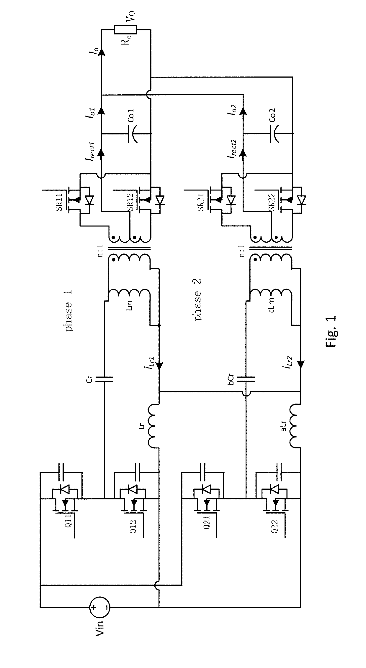
[0045]In the common-inductor current-sharing method for multi-phase LLC resonant converter of the preferred embodiments of the present invention, the series resonant inductors in each phase are connected in parallel. No additional components are needed to achieve current sharing. Analysis of the common-inductor current-sharing method shows that the relative resonant current is significantly reduced. Simulated and experimental results show that the resonant current error is reduced by 63 times and is only 0.44% at 600 W total load power. As a comparative example, a common-capacitor current-sharing method is also discussed. The common-capacitor current-sharing method is only able to achieve a resonant current error of 5% at 600 W total load power as shown in FIG. 32. The LLC resonant converter shown in FIG. 30 can only achieve a resonant current error of 27% at 600 W total load power.

[0046]FIG. 1 shows a two-phase LLC resonant converter using the common-inductor current-sharing method...


PUM


Abstract

An LLC resonant converter includes a first phase with a first primary circuit and a second phase with a second primary circuit. The first primary circuit includes a first shared inductor, and the second primary circuit includes a second shared inductor. The first and second shared inductors are connected in parallel with each other. The first and second primary circuits do not include a capacitor that is connected in parallel with each other.

Description

BACKGROUND OF THE INVENTION[0001]1. Field of the Invention[0002]The present invention relates to high-efficiency power supplies and similar devices.[0003]2. Description of the Related Art[0004]A multi-phase, parallel resonant converter is a good choice for high-efficiency, high-power DC / DC applications, such as telecommunication power supplies and similar applications. Load current sharing is a key issue in such applications. Interleaved, parallel power converters can provide an output with a small ripple. However, interleaved, parallel power supplies need additional metal-oxide-semiconductor field-effect transistors (MOSFETs), and therefore, the cost of interleaved, parallel power supplies is higher, and an additional gate-drive circuit is needed. The dynamic performance of interleaved, parallel power is not very good when the load is changing. In particular, at light loads, interleaved, parallel power can be inefficient because of switching losses of all of the MOSFETs.[0005]Known...

Claims


Application Information

Patent Timeline
Patent Type & Authority Patents(United States)
IPC IPC(8): H02M3/335H02M3/28
CPCH02M3/33592H02M3/285H02M3/33576H02M3/3376Y02B70/10H02M1/0058
Inventor WANG, HONGLIANGCHEN, YANGLIU, YAN-FEIAFSHARIAN, JAHANGIRYANG, ZHIHUAGONG, BING
Owner MURATA MFG CO LTD
Why Eureka
Try Eureka