
Field device

a field device and field technology, applied in the field of field devices, can solve the problems of difficult to accurately acquire only digital signals converted in synchronization with certain cyclic signals, difficult to accurately acquire only digital signals within specific specifics, etc., to achieve accurate and easy acquisition

Active Publication Date: 2019-12-03
YOKOGAWA ELECTRIC CORP
View PDF16 Cites 0 Cited by
  • Summary
  • Abstract
  • Description
  • Claims
  • Application Information

AI Technical Summary

Benefits of technology

This approach enables the accurate and easy acquisition of digital signals in synchronization with cyclic signals, even with ΔΣ type A / D converters, effectively mitigating the impact of differential noises.

Problems solved by technology

In all these A / D converters, there occurs a delay (a group delay) corresponding to a time required for a conversion process of converting analog signals to digital signals.
However, the ΔΣ type A / D converter cannot control the sampling section as in the successive comparison type A / D converter, and the digital signals are continuously output from the ΔΣ type A / D converter.
For this reason, there are some cases where, in a field device including an A / D converter (the A / D converter at which the group delay occurs, which cannot control the sampling section and continues to perform the conversion process) like the ΔΣ type A / D converter, it is difficult to accurately acquire only digital signals converted in synchronization with certain cyclic signals.
However, there are some cases where, if an A / D converter provided in the electromagnetic flowmeter is, for example, the ΔΣ type A / D converter, it is difficult to accurately acquire only digital signals within the specific section for the aforementioned reason.

Method used


Image

  • Field device
  • Field device
  • Field device

Examples


Embodiment Construction

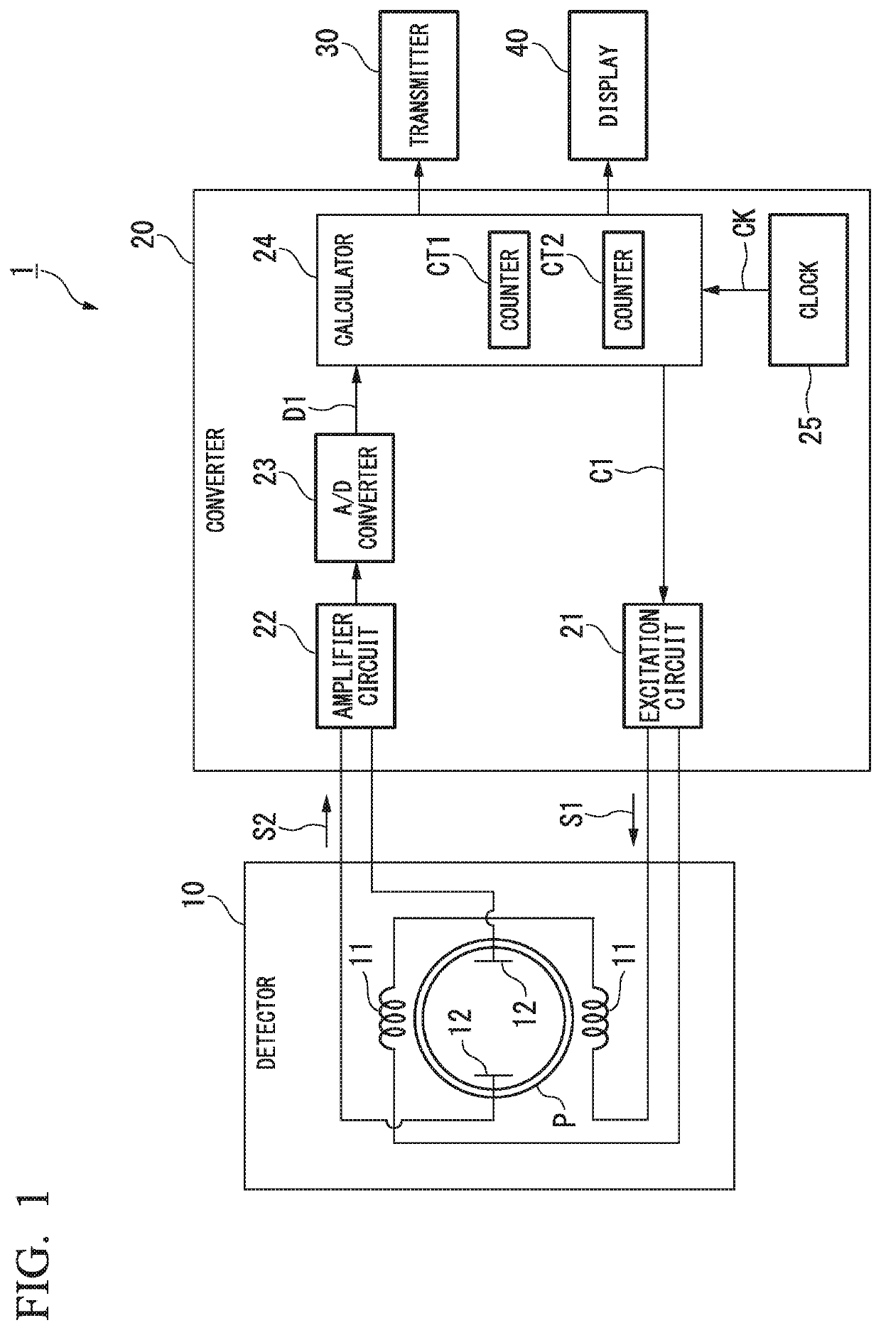
[0037]Hereinafter, a field device according to an embodiment of the present invention will be described in detail with reference to the drawings. In the following, to facilitate understanding, as the field device, an electromagnetic flowmeter for measuring a flow rate of a fluid flowing in a pipe will be described by way of example. However, the present invention is not limited to this electromagnetic flowmeter, and it may be applied to arbitrary field devices (measures and operating devices).

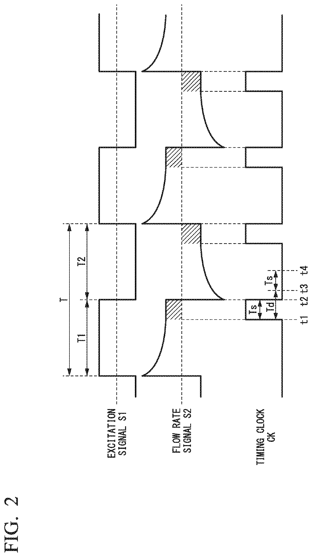
[0038]FIG. 1 is a block diagram showing constitutions of main components of an electromagnetic flowmeter acting as a field device according to an embodiment of the present invention. As shown in FIG. 1, an electromagnetic flowmeter (a field device) 1 includes, for example, a detector (a sensor) 10, a converter 20, a transmitter (an output) 30, and a display (an output) 40. The electromagnetic flowmeter 1 detects an electromotive force (an electromotive force proportional to a flow velocity) gen...


PUM


Abstract

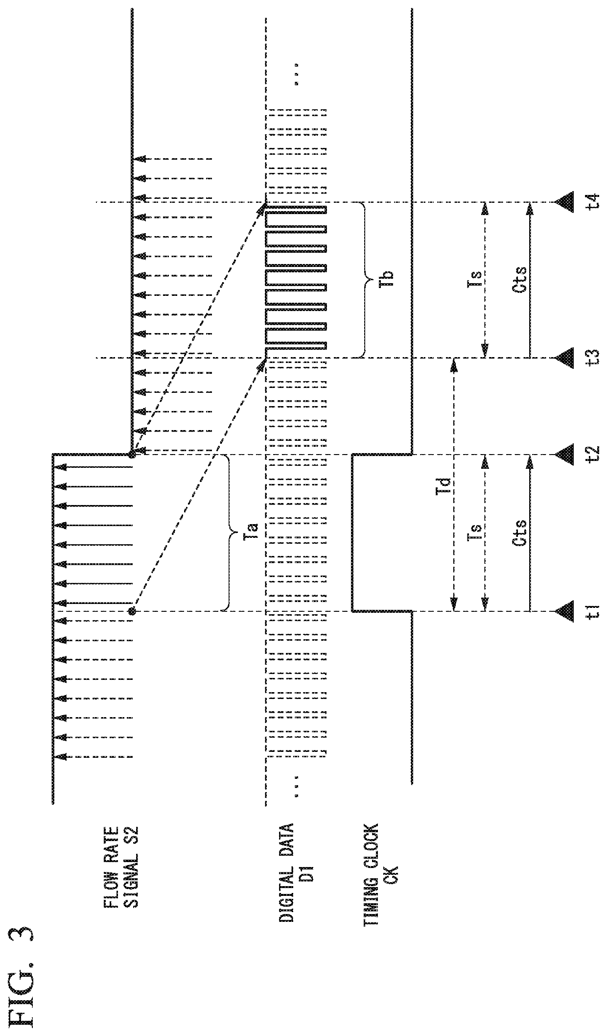
A field device according to one aspect of the present invention includes a sensor, an analog-digital converter configured to continuously convert detected signals output from the sensor to digital signals, and a calculator configured to convert the digital signals to process values. The calculator starts acquisition of the digital signals output from the analog-digital converter at a first point in time that is delayed by a processing time required for the conversion process of the analog-digital converter from a start point of a timing signal defining a sampling section of the detected signals, and finishes the acquisition of the digital signals output from the analog-digital converter at a second point in time that is delayed by the processing time from an end point of the timing signal.

Description

BACKGROUND OF THE INVENTION[0001]Field of the Invention[0002]The present invention relates to a field device.[0003]Priority is claimed on Japanese Patent Application No. 2015-089313, filed Apr. 24, 2015, the contents of which are incorporated herein by reference.[0004]Description of Related Art[0005]In a plant or a factory or the like, a distributed control system (DCS) has been implemented to realize a high level of automated operation. In the DCS, on-site devices, which are referred to as field devices, are connected via a communication means to controllers, which control the field devices. The field devices used in the DCS are classified into measures such as flowmeters and temperature sensors, and operating devices such as valve devices and actuator devices.[0006]The measure that is a type of the field device generally includes sensors that detect a variety of state quantities (e.g., flow rate, temperature, etc.), an amplifier that amplifies detection signals of the sensors, an ...

Claims


Application Information

Patent Timeline
Patent Type & Authority Patents(United States)
IPC IPC(8): G01F1/58G05B19/042H03M3/00
CPCH03M3/458G01F1/588G05B19/0423G05B2219/49023G05B2219/21137G05B23/0213G05B2219/24065G05B21/02
Inventor IWASHITA, JUNICHISHIMURA, TORUHARIGANE, DAISUKELI, WANDONG
Owner YOKOGAWA ELECTRIC CORP
Learn More