Bias circuit and power amplifier circuit

a power amplifier circuit and bias technology, applied in amplifiers, amplifier types, amplifiers with semiconductor devices/discharge tubes, etc., can solve the problems of distorted output signals and drop in linearity of power amplifier circuits

Active Publication Date: 2019-12-03
AIROHA TECHNOLOGY CORPORATION
View PDF7 Cites 3 Cited by
  • Summary
  • Abstract
  • Description
  • Claims
  • Application Information

AI Technical Summary

Benefits of technology

[0003]A bias circuit normally provides a voltage signal or a current signal to an input node of a power amplifier circuit to be used as a bias signal of the power amplifier circuit. However, when the input signal of the power amplifier circuit is at a high-power state, the linearity of the power amplifier circuit will drop and the output signal will be distorted. Therefore, it has become a prominent task for the industries to provide a new bias circuit capable of providing compensation to avoid the linearity of the power amplifier circuit dropping when the input signal of the power amplifier circuit is at the high-power state.

Problems solved by technology

However, when the input signal of the power amplifier circuit is at a high-power state, the linearity of the power amplifier circuit will drop and the output signal will be distorted.

Method used


Image

  • Bias circuit and power amplifier circuit
  • Bias circuit and power amplifier circuit
  • Bias circuit and power amplifier circuit

Examples


first embodiment

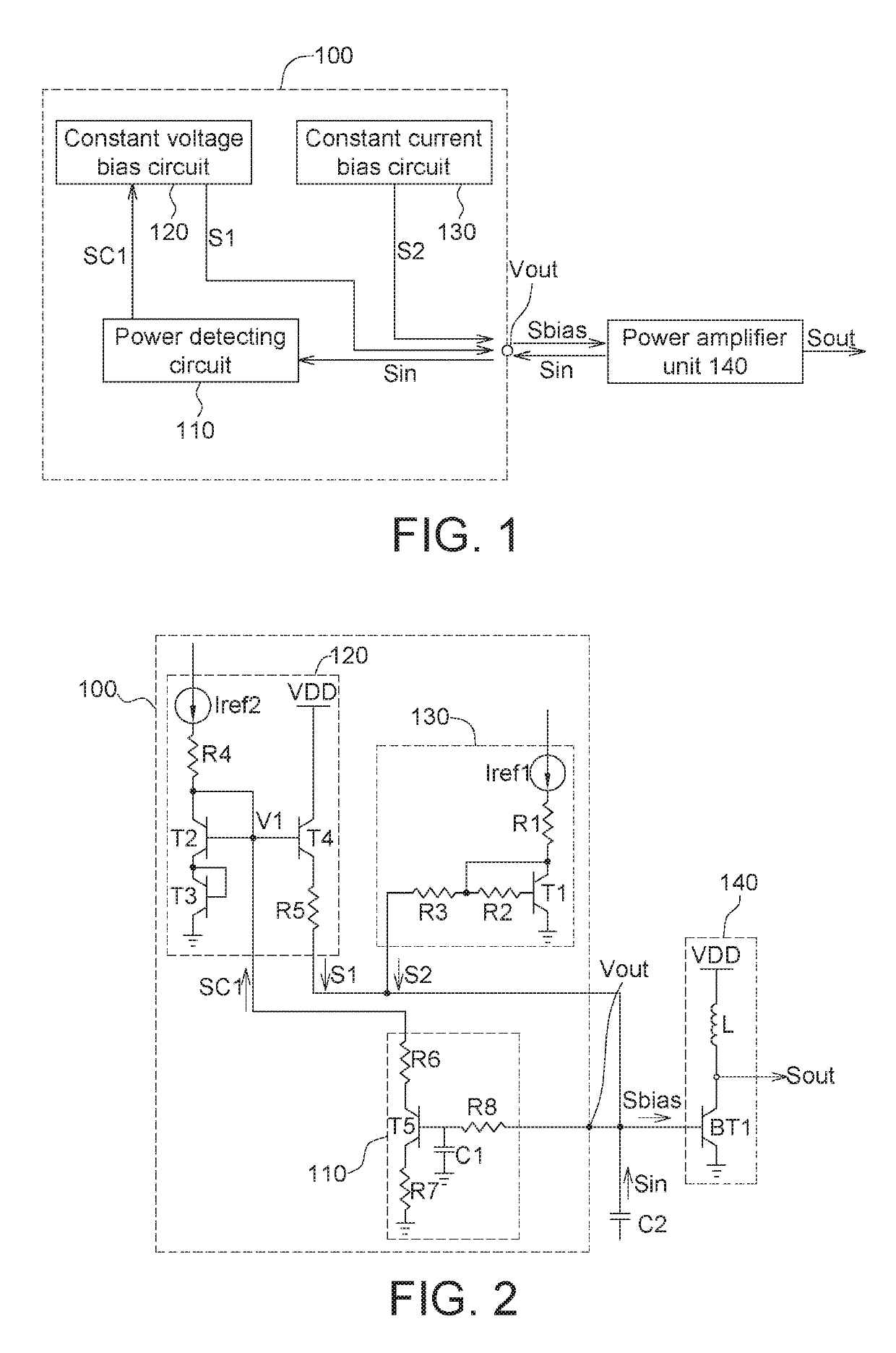
[0013]FIG. 1 shows a block diagram of a bias circuit 100 according to the present disclosure. The bias circuit 100 includes an output node Vout, a power detecting circuit 110, a constant voltage bias circuit 120, and a constant current bias circuit 130. The output node Vout is configured to provide a bias signal Sbias to a power amplifier unit 140 and receive an input signal Sin of the power amplifier unit 140. The power detecting circuit 110 detects a power of the input signal Sin of the power amplifier unit 140 to provide a control signal SC1. The constant voltage bias circuit 120 is configured to selectively provide a first signal S1 to the output node Vout according to control signal SC1. The constant current bias circuit 130 provides a second signal S2 to the output node Vout.

[0014]In the present disclosure, the power amplifier unit 140 generates an output signal Sout according to the input signal Sin, such as a radio frequency signal. The power detecting circuit 110 detects a ...

second embodiment

[0024]FIG. 5 shows a circuit diagram of a bias circuit 200 according to the present disclosure. The bias circuit 200 of FIG. 5 is different from the bias circuit 100 of FIG. 2 in that the bias circuit 200 further includes another constant voltage bias circuit 150. The circuit structure of the constant voltage bias circuit 150 is identical to the circuit structure of the constant voltage bias circuit 120, and the similarities are not repeated here. In the present embodiment, the power detecting circuit 210 of FIG. 5 further provides a control signal SC2 to the constant voltage bias circuit 150 according to the power of the input signal Sin of the power amplifier unit 140 and makes the constant voltage bias circuit 150 selectively provide a third signal S3 to the output node Vout of the bias circuit 200 according to the control signal 502.

[0025]In the present embodiment, the power detecting circuit 210 of FIG. 5 is different from the power detecting circuit 110 of FIG. 2 in that the p...


PUM


Abstract

A bias circuit and a power amplifier circuit are provided in the present disclosure. The bias circuit includes an output node, a power detecting circuit, a first constant voltage bias circuit, and a constant current bias circuit. The output node is configured to provide a bias signal to a power amplifier unit. The output node is further configured to receive an input signal of the power amplifier unit. The power detecting circuit is configured to detect a power of the input signal of the power amplifier unit to provide a first control signal. The first constant voltage bias circuit is configured to selectively provide a first signal to the output node according to the first control signal. The constant current bias circuit provides a second signal to the output node.

Description

[0001]This application claims the benefit of Taiwan application Serial No. 106129822, filed Aug. 31, 2017, the subject matter of which is incorporated herein by reference.BACKGROUND OF THE PRESENT DISCLOSUREField of the Present Disclosure[0002]The present disclosure relates in general to a bias circuit and a power amplifier circuit.Description of the Related Art[0003]A bias circuit normally provides a voltage signal or a current signal to an input node of a power amplifier circuit to be used as a bias signal of the power amplifier circuit. However, when the input signal of the power amplifier circuit is at a high-power state, the linearity of the power amplifier circuit will drop and the output signal will be distorted. Therefore, it has become a prominent task for the industries to provide a new bias circuit capable of providing compensation to avoid the linearity of the power amplifier circuit dropping when the input signal of the power amplifier circuit is at the high-power state...

Claims


Application Information

Patent Timeline
Patent Type & Authority Patents(United States)
IPC IPC(8): H03F1/02H03F3/21H03F3/193
CPCH03F1/0222H03F3/21H03F2200/216H03F2200/105H03F2200/21H03F1/32H03F2200/375H03F1/0261H03F1/302H03F3/191H03F3/245H03F2200/18H03F2200/451
Inventor TSAI, LI-FAN
Owner AIROHA TECHNOLOGY CORPORATION
Why Eureka
Try Eureka