Cooperative and parasitic radio access networks

Active Publication Date: 2019-12-03
TYBALT LLC
View PDF27 Cites 8 Cited by
  • Summary
  • Abstract
  • Description
  • Claims
  • Application Information

AI Technical Summary

Benefits of technology

This patent is about a system that can be used in an urban battlefield to avoid detection by enemy combatants and reduce vulnerability to attacks and service disruptions. The system can operate by exploiting control signaling and resource scheduling of a native legacy network under enemy control. This helps to decentralize network control and access to resources, ultimately making the warfighter network safer and more resilient.

Problems solved by technology

Fading and interference are the two key challenges faced by designers of wireless communication systems.
While fading limits the coverage and reliability of any point-to-point wireless connection, e.g., between a base station and a mobile terminal, interference in prior-art networks restricts the reusability of the spectral resource (time, frequency slots, multiple-access codes, etc.) in space, thus limiting the overall spectral efficiency.
However, this approach presents its own limitations, as denser infrastructure results in more interference.
In practice, such systems suffer from diminishing returns.
Due to the limited space at an access point or cell site, additional antennas cause more correlation between channels, resulting in less capacity benefit for each additional antenna.
In such cases, the ratio of cost to spectral efficiency rises exponentially.
As explained above, a key problem faced by cellular network providers is that legacy infrastructure costs increase exponentially relative to capacity, which means that providers don't benefit from economies of scale.
Also, legacy network costs increase exponentially with the data rate per user.
This stifles innovation and keeps prices high, leaving consumers stuck with Third-World-quality service.
Furthermore, cellular providers are locked into long-term contracts with hardware manufacturers that strongly discourage, if not outright prohibit, third-party improvements to the network infrastructure.

Method used


Image

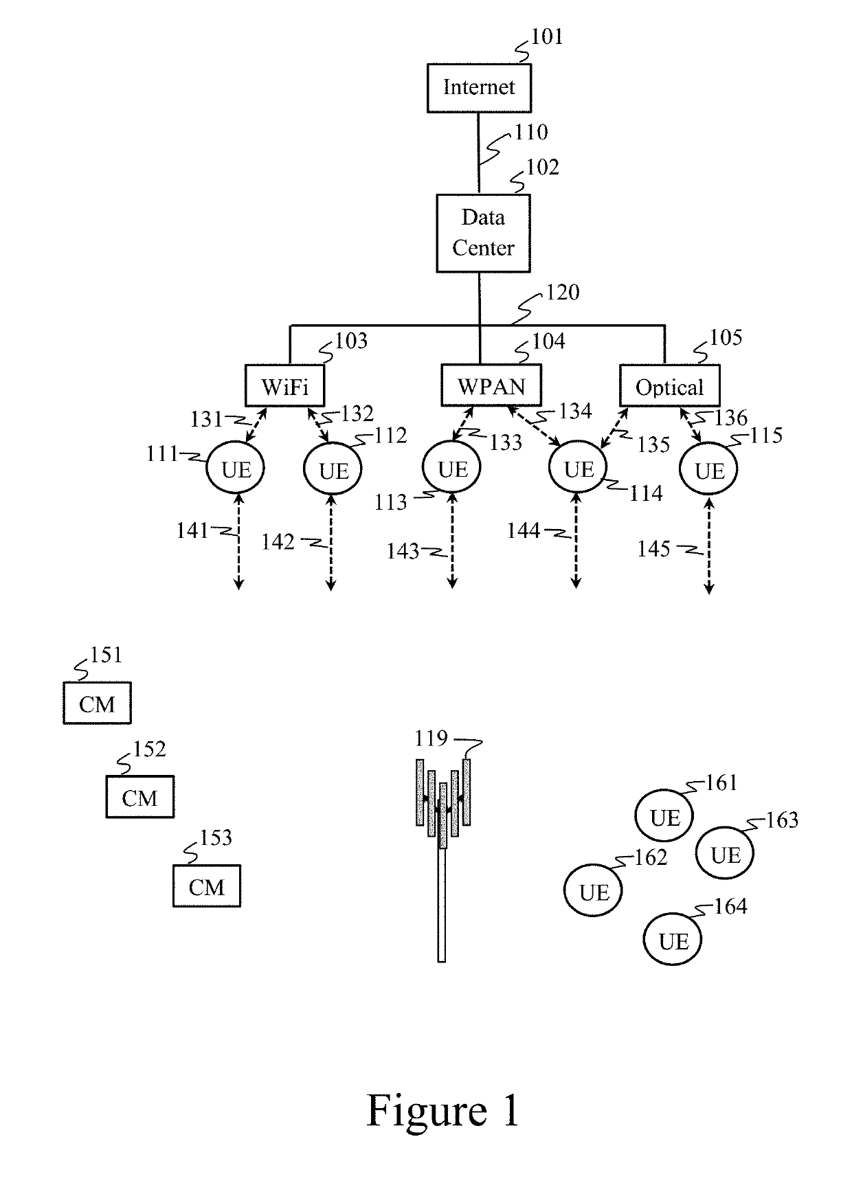
  • Cooperative and parasitic radio access networks
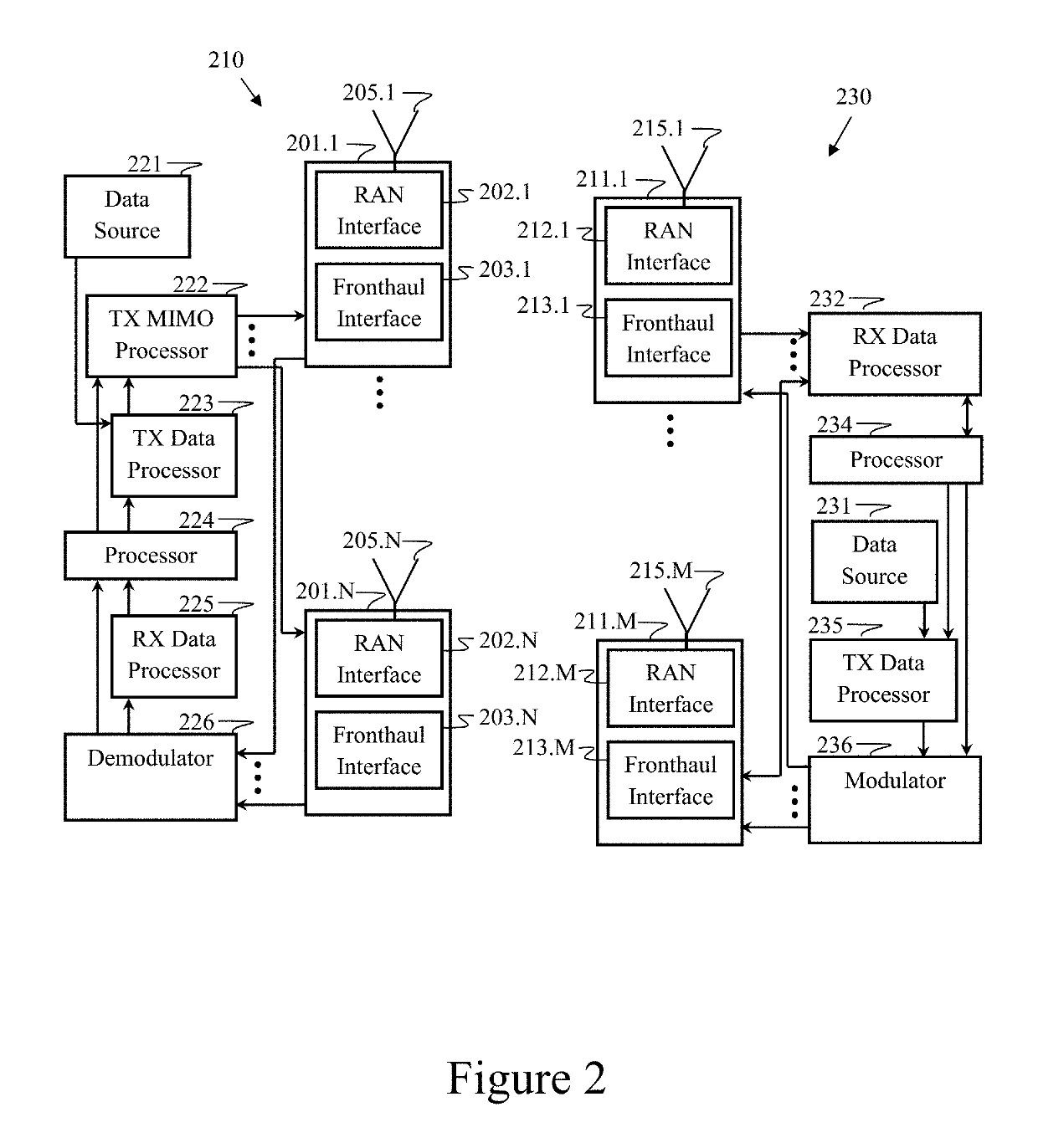
  • Cooperative and parasitic radio access networks
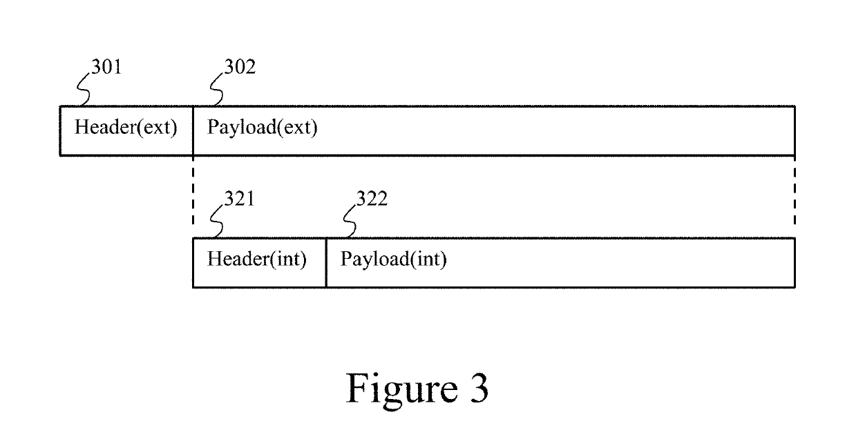
  • Cooperative and parasitic radio access networks

Examples


Embodiment Construction

[0054]The detailed description set forth below in connection with the appended drawings is intended as a description of various aspects of the present work and is not intended to represent the only aspects in which the present work may be practiced. The detailed description includes specific details for the purpose of providing a thorough understanding of the present work. However, it will be apparent to those skilled in the art that the present work may be practiced without these specific details. In some instances, well known structures and components are shown in block diagram form in order to avoid obscuring the concepts of the present work.

[0055]Where each aspect of the disclosure might represent a single combination of elements, the present work is considered to include all possible combinations of the disclosed elements. Thus if one aspect comprises elements A, B, and C, and a second aspect comprises elements B and D, then the present work is also considered to include other ...


PUM


Abstract

A wireless user equipment (UE) device obtains uplink and / or downlink grants for control and data communications from a base station in a first network and configures a secondary network link for device-to-device (D2D) communications between the UE device and another UE device operating in a second network. The secondary network link employs a spectrum resource allocated for the uplink and / or downlink grants in the first network. The UE device can comprise a first-network controller that inserts first-network control signals into a control portion of a frame, an application-layer processor that inserts user data into a data payload portion of the frame, and a second-network controller communicatively coupled to the application-layer processor that inserts second-network control signals into the data payload portion of the frame. This can allow a transmission to be processed by networks that employ different radio access network technologies.

Description

CROSS-REFERENCE TO RELATED APPLICATIONS[0001]This application is a Continuation in Part of U.S. patent application Ser. No. 15 / 268,992, entitled “Sharing Resources Between Wireless Networks,” filed Sep. 19, 2016, which is Continuation of U.S. patent application Ser. No. 14 / 498,499, entitled “Sharing Resources Between Wireless Networks,” filed Sep. 26, 2014, now U.S. Pat. No. 9,473,226, which is a Continuation in Part of U.S. patent application Ser. No. 13 / 757,032, entitled “LPI / LPD Communication Systems,” filed on Feb. 1, 2013, now U.S. Pat. No. 8,929,550, which claims priority under 35 U.S.C. 119(e) to U.S. Provisional Application Ser. No. 61 / 594,086, entitled “LPI / LPD Communication Systems,” filed Feb. 2, 2012. This application claims priority under 35 U.S.C. 119(e) to U.S. Provisional Application Ser. No. 62 / 252,717, entitled “Cooperative and Parasitic Radio Access Networks,” filed Nov. 9, 2015.BACKGROUND[0002]I. Field[0003]The present invention relates generally to wireless comm...

Claims


Application Information

Patent Timeline
IPC IPC(8): H04W72/12H04W88/06
CPCH04W72/1215H04W88/06H04L63/0435H04L63/061H04B7/024H04B7/0452H04W76/14H04L5/0037H04W76/16H04W72/54H04W12/04H04W12/08
Inventor SHATTIL, STEVE
Owner TYBALT LLC
Why Eureka
Try Eureka