Distributed monitoring and control system

Active Publication Date: 2010-09-07
EMNET INC +1
View PDF75 Cites 41 Cited by
  • Summary
  • Abstract
  • Description
  • Claims
  • Application Information

AI Technical Summary

Benefits of technology

[0006]The present subject-matter provides a distributed monitoring and control system. The distributed monitoring and control system may be implemented to reduce the occurrence of combined sewer overflow. The distributed monitoring and control system includes a plurality of nodes, each of which includes a processor, a memory and a transceiver. The system includes a plurality of nodes, including nodes having different functions, such as rNodes, iNodes, aNodes and gNodes. Each of the nodes provides interconnectivi

Problems solved by technology

A CSO occurs when a wastewater treatment facility experiences excessive inflow due to wet weather conditions resulting in an overflow or discharge of contaminated water.
Accordingly, a CSO event often results in the contamination or rivers, lakes and ocean shores and presents numerous environmental health-related dangers.
However, these solutions require intensive and expensive construction, which can be disruptive to cities and their population.
Moreover,

Method used


Image

  • Distributed monitoring and control system
  • Distributed monitoring and control system
  • Distributed monitoring and control system

Examples


Embodiment Construction

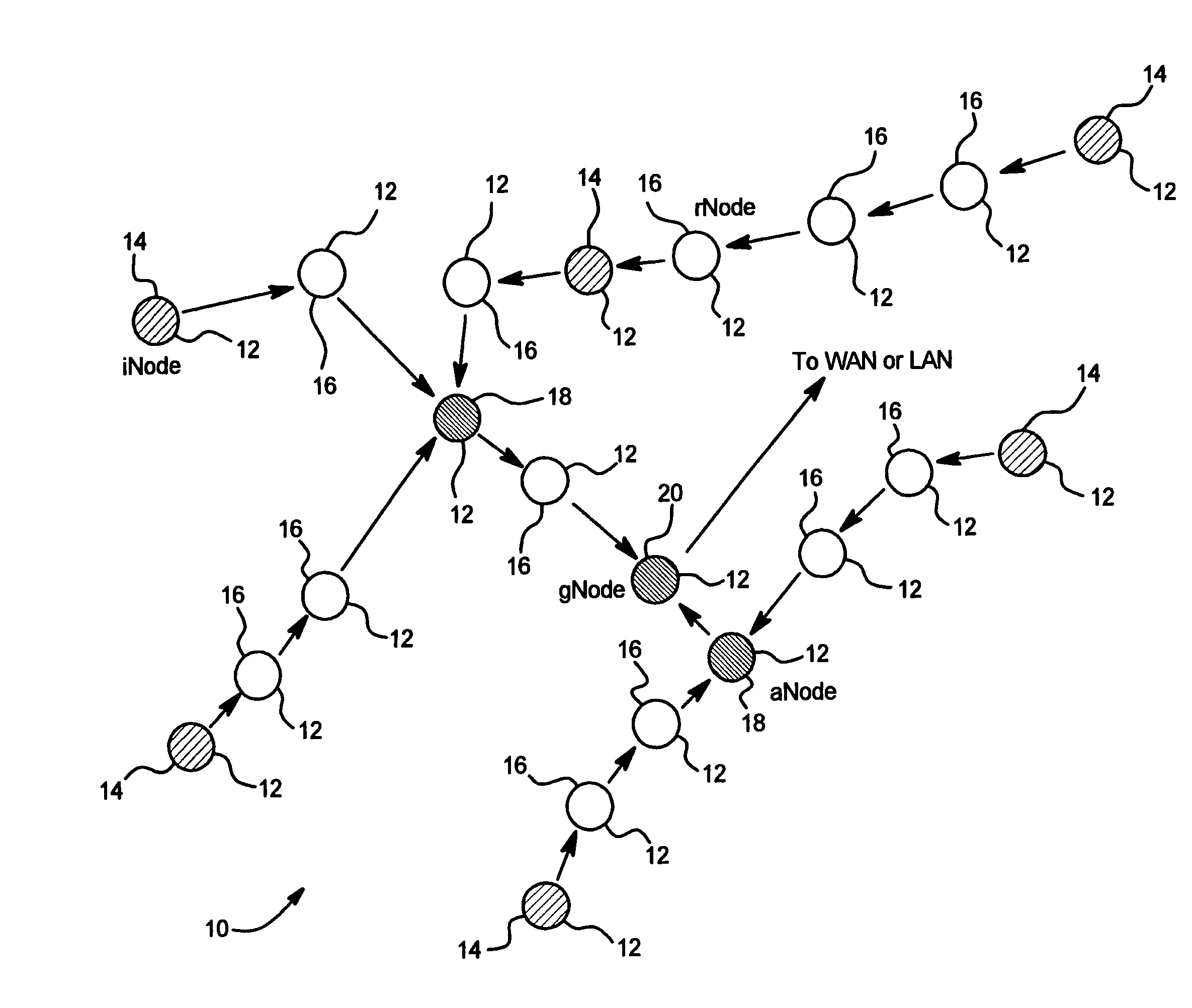
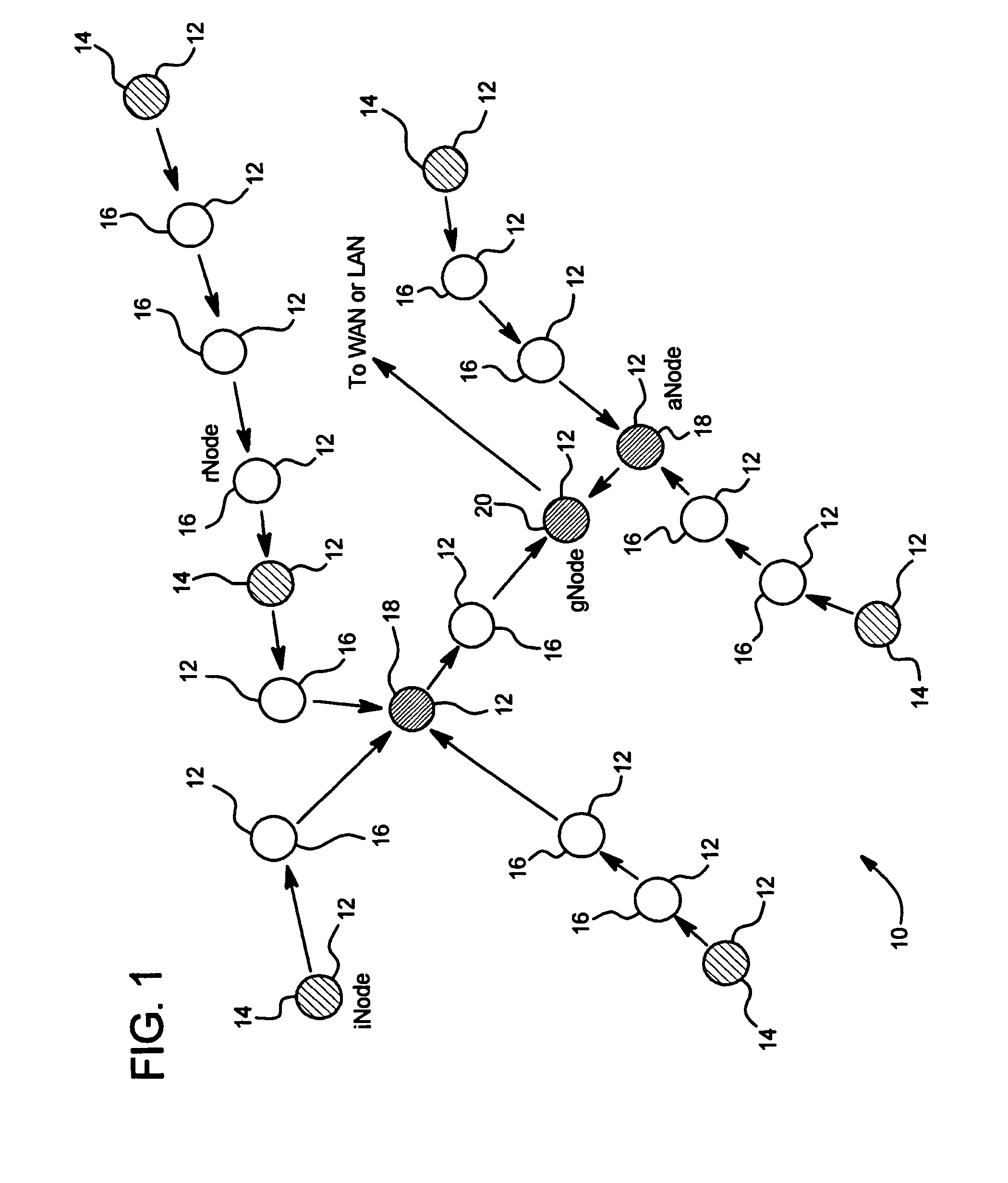
[0023]FIG. 1 schematically illustrates a distributed monitoring and control system 10 for monitoring and controlling flow in a combined sewer system. As shown in FIG. 1, the distributed monitoring and control system 10 includes a plurality of intercommunicating nodes 12. In the distributed monitoring and control system 10 shown in FIG. 1, there are sensor nodes (iNodes) 14, routing nodes (rNodes) 16, actuator nodes (aNodes) 18 and gateway nodes (gNodes) 20. In the example shown in FIG. 1, the communication between the nodes 12 is achieved using a wireless transceiver in each of the nodes 12, as described further below. Although the preferred embodiment of the distributed monitoring and control system 10 described herein is a wireless system, it is contemplated that wired or hybrid (wired and wireless combination) communication may be utilized to accomplish the distributed monitoring and control system 10.

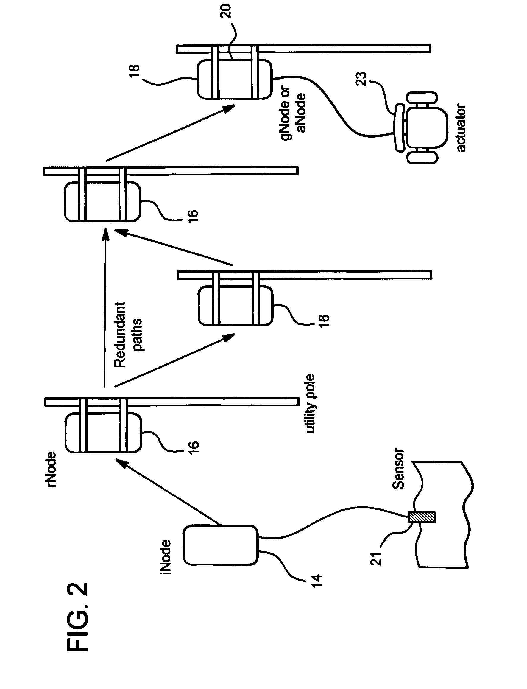
[0024]As shown in FIG. 2, the iNode 14 collects information from a sensor 21. T...


PUM


Abstract

A distributed monitoring and control system includes a plurality of nodes forming a redundant communication network. Each of the nodes includes a processor, a memory and a transceiver. At least one of the nodes includes a sensor for acquiring information. At least one of the nodes includes an actuator. At least one of the processors is programmed with a control algorithm to receive information acquired from the sensors, calculate a control command and communicate the control command to the actuators for execution.

Description

CROSS REFERENCE TO RELATED APPLICATIONS[0001]The present application claims the benefit of U.S. Provisional Application No. 60 / 682,384, filed May 19, 2005.TECHNICAL FIELD[0002]The present subject-matter generally relates to a distributed monitoring and control system. More specifically, the present subject-matter relates to a system using distributed monitoring and control of combined sewer systems to reduce combined sewer overflow conditions.BACKGROUND OF THE INVENTION[0003]In many cities wastewater and rainwater are collected together in a combined sewer system. These combined sewer systems create a potential for a combined sewer overflow (CSO). A CSO occurs when a wastewater treatment facility experiences excessive inflow due to wet weather conditions resulting in an overflow or discharge of contaminated water. In some cases, the overflow water backs up into homes or businesses. In order to prevent raw sewage backup into homes and businesses, waste water treatment facilities ofte...

Claims


Application Information

Patent Timeline
IPC IPC(8): H04L12/00E02B13/00
CPCE03F7/00H04L45/00H04W40/00H04L67/125
Inventor MONTESTRUQUE, LUIS A.LEMMON, MICHAEL D.TALLEY, JEFFREY W.
Owner EMNET INC
Why Eureka
Try Eureka