Techniques for optimizing orientation of models for three-dimensional printing

a three-dimensional printing and orientation optimization technology, applied in the field of computer science, can solve the problems of increasing the likelihood of a user creating 3d objects that exhibit undesirable characteristics or design flaws, introducing significant structural anisotropy, and the process employed by the 3d printer oftentimes introduces weaknesses in the corresponding 3d object that are not predicted, so as to reduce the fragility and automatically and efficiently mitigate undesirable weaknesses

Active Publication Date: 2015-06-04
AUTODESK INC
View PDF7 Cites 42 Cited by
  • Summary
  • Abstract
  • Description
  • Claims
  • Application Information

AI Technical Summary

Benefits of technology

[0010]One advantage of the disclosed printing orientation optimization techniques is that these techniques automatically and efficiently mitigate undesirable weaknesses imbued into the 3D object by the manufacturing process. In particular, selecting the identified optimal printing direction for 3D printers that implement the Fused Deposition Method reduces the fragility between manufactured layers by orienting weak areas along the axis of the print bed.

Problems solved by technology

However, some design issues inherent in manufacturing 3D models are inadequately detected using conventional modeling tools, thereby increasing the likelihood of a user creating 3D objects that exhibit undesirable characteristics or design flaws.
In particular, the manufacturing process employed by the 3D printer oftentimes introduces weaknesses into the corresponding 3D object that are not predicted by conventional modelling tools.
Such a layer-by-layer construction can introduce significant structural anisotropy.
In particular, vertical bonding between layers is typically much weaker than in-layer bonding.
Consequently, manufacturing using FDM often infuses unacceptable weaknesses between layers in the 3D object.
Current modelling tools do not provide a good way to address these issues, which can result in objects manufactured via 3D printing that are inadvertently fragile.

Method used


Image

  • Techniques for optimizing orientation of models for three-dimensional printing
  • Techniques for optimizing orientation of models for three-dimensional printing
  • Techniques for optimizing orientation of models for three-dimensional printing

Examples


Embodiment Construction

[0019]In the following description, numerous specific details are set forth to provide a more thorough understanding of the present invention. However, it will be apparent to one of skill in the art that the present invention may be practiced without one or more of these specific details.

System Overview

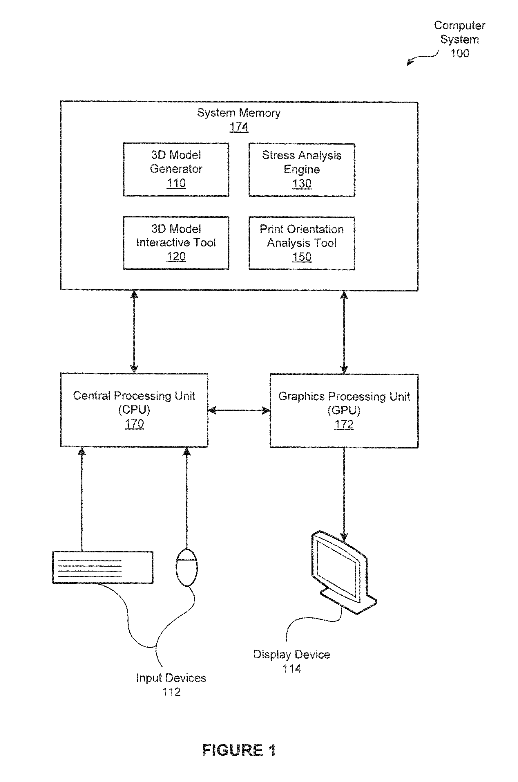
[0020]FIG. 1 is a block diagram illustrating a computer system 100 configured to implement one or more aspects of the present invention. As shown, the computer system 100 includes, without limitation, a central processing unit (CPU) 170, a system memory 174, a graphics processing unit (GPU) 172, input devices 112, and a display device 114.

[0021]The CPU 170 receives input user information from the input devices 112, such as a keyboard or a mouse. In operation, the CPU 170 is the master processor of the computer system 100, controlling and coordinating operations of other system components. In particular, the CPU 170 issues commands that control the operation of the GPU 172. The GPU 172...


PUM

PropertyMeasurementUnit
applied forceaaaaaaaaaa
forceaaaaaaaaaa
structural stressaaaaaaaaaa

Abstract

In one embodiment of the present invention, a print orientation tool efficiently determines an orientation of a three-dimensional (3D) model such that, when 3D printed, the structural integrity of the resulting 3D object is optimized. In operation, the print orientation tool configures a stress analysis engine to slice the 3D model into two-dimensional (2D) cross-sections. The stress analysis engine then compute structural stresses associated with the 2D cross-sections. The print orientation tool translates the structural stresses to weakness metrics. Subsequently, the print orientation tool evaluates the orientations of the cross-sections in conjunction with the corresponding weakness metrics to select a printing orientation that minimizes weaknesses in the 3D model. Advantageously, by aligning the 3D model to the print bed based on the optimized printing orientation, the user mitigates weaknesses in the corresponding 3D object attributable to the 3D printing manufacturing process.

Description

CROSS-REFERENCE TO RELATED APPLICATIONS[0001]This application claims benefit of the U.S. Provisional Patent Application having Ser. No. 61 / 911,311 (Attorney Docket Number AUTO / 1306USL) and filed on Dec. 3, 2013. The subject matter of this related application is hereby incorporated herein by reference.BACKGROUND OF THE INVENTION[0002]1. Field of the Invention[0003]Embodiments of the present invention relate generally to computer science and, more specifically, to techniques for optimizing orientation of models for three-dimensional printing.[0004]2. Description of the Related Art[0005]Democratized digital manufacturing devices, such as desktop three-dimensional (3D) printers, enable non-professional users to casually create physical objects based on 3D printable digital models. To streamline the creation and optimization of 3D models, various modeling tools provide useful feedback and guidance during portions of the design process. For example, designers may use a sculpting brush in ...

Claims


Application Information

Patent Timeline
Patent Type & Authority Applications(United States)
IPC IPC(8): G06F17/50B29C67/00
CPCG06F17/50B33Y50/02B29C67/0088B29C64/386B29C64/40G05B19/4099G05B2219/49038G06F30/00G06F2119/18Y02P90/02
Inventor SCHMIDT, RYAN MICHAELUMETANI, NOBUYUKI
Owner AUTODESK INC
Why Eureka
Try Eureka