
Separator for electrochemical device

a technology of electrochemical devices and separators, which is applied in the manufacture of final products, cell components, cell component details, etc., can solve the problems of electrochemical devices that fail to get certification, electrochemical devices are not used, and have poor etc., to achieve improved mechanical and thermal properties, good air permeability, and small diameter

Active Publication Date: 2019-12-10
LG CHEM LTD
View PDF35 Cites 0 Cited by
  • Summary
  • Abstract
  • Description
  • Claims
  • Application Information

AI Technical Summary

Benefits of technology

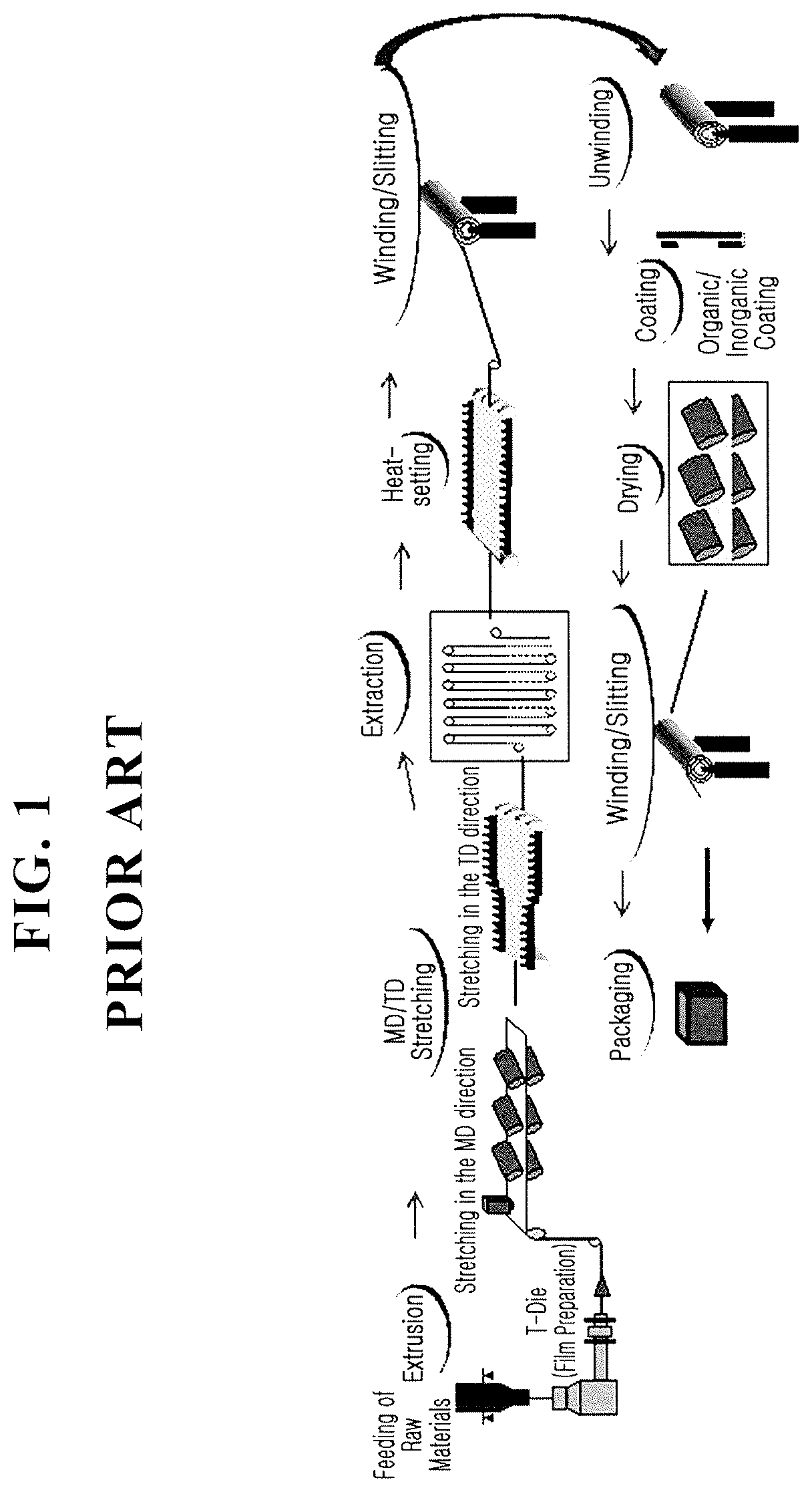
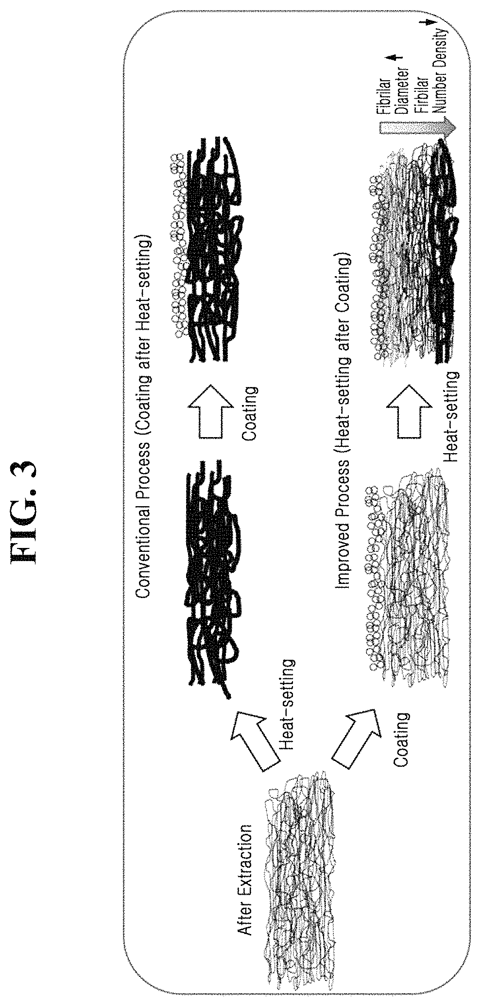
[0034]According to one embodiment of the present disclosure, a porous polyolefin film is coated by way of slurry coating that allows heat-setting at a higher temperature than a conventional heat-setting temperature, thereby providing a composite separator having improved mechanical and thermal properties and good air permeability.
[0035]Also, since the composite separator having a porous coating layer is prepared through slurry coating and heat-setting, heat applied in heat-setting is transferred from the porous coating layer to the polyolefin film, thereby allowing heat-setting at a relatively high temperature and eventually improving the wetting property of the coating slurry to the fibril structure of the polyolefin film.
[0036]In addition, since the heat applied in heat-setting is transferred from the porous coating layer to the polyolefin film, the polyolefin film has fibrils with a smaller diameter, has increased fibrilar number density per unit area and has increased interface contact area with a coating slurry forming the porous coating layer. Thereby, the polyolefin film easily maintains its physical form to improve the heat shrinkage rate of the composite separator and to enhance the peeling force of the coating layer.

Problems solved by technology

However, the high porous separator has very poor mechanical and thermal properties.
Particularly, the separator fails to suppress thermal propagation during safety tests (impact, nail penetration, hot box and so on), thereby causing ignition and explosion on heating.
For this reason, in spite of electrochemical devices having good performances, the electrochemical devices often fail to get certification and are not used.
The separator consisting of only such a substrate has poor thermal / mechanical properties.

Method used


Image

  • Separator for electrochemical device
  • Separator for electrochemical device
  • Separator for electrochemical device

Examples


example 1-2

of Coin Cell

[0146]1.0M LiPF6 was added in an organic solvent of ethylene carbonate / ethyl methyl carbonate (1:2, vol / vol), to obtain an electrolyte solution. The separator was sufficiently wet in the electrolyte solution, and the separator was used to prepare a coin cell.

example 2-1

of Separator

[0147]In order to prepare a slurry for a porous coating layer, 0.5 μm-average diameter organic particles (Zeon, FX9022) consisting of a crosslinked polymer of butylacrylate and ethylmethacrylate, polybutylacrylate as a binder polymer, carboxylmethyl cellulose (CMC) as a dispersant, and water as a solvent were mixed in a weight ratio of 18 / 1.5 / 0.5 / 80. After the plasticizer was extracted, the slurry was coated on one surface of the porous polyolefin film in a thickness of 3.5 μm, and heat-setting was carried out at 132.5° C. and 5 m / min, to obtain a 14.5 μm-thick separator having a porous coating layer. The porous coating layer of the separator obtained had an average pore size of 0.5 μm and an average porosity of 60%.

example 2-2

of Coin Cell

[0148]The procedures of Example 1-2 were repeated except that the separator of Example 2-1 was used to prepare an electrochemical device.


PUM

PropertyMeasurementUnit
thicknessaaaaaaaaaa
heat-shrinkage rateaaaaaaaaaa
electrical resistanceaaaaaaaaaa

Abstract

The present disclosure provides a separator for an electrochemical device, comprising: a porous polymer film; and a porous coating layer formed on one or both surfaces of the porous polymer film and comprising at least one of inorganic particles and organic particles, and a binder polymer, wherein fibrils in the surface of the porous polymer film are entangled with the particles in the porous coating layer in the contact surface between the porous polymer film and the porous coating layer, and the separator has an air permeability of 100 to 800 sec / 100 cc, an electrical resistance of 0.5 to 1.5Ω, and a heat-shrinkage rate of 8% or less in each of machine and transverse directions, and an electrochemical device having the same.

Description

TECHNICAL FIELD[0001]The present disclosure relates to a separator for an electrochemical device, more specifically a separator for an electrochemical device which has improved mechanical and thermal properties.[0002]This application claims priority to Korean Patent Application No. 10-2013-0134302 filed in the Republic of Korea on Nov. 6, 2013, which is incorporated herein by reference.[0003]Also, this application claims priority to Korean Patent Application No. 10-2013-0151551 filed in the Republic of Korea on Dec. 6, 2013, which is incorporated herein by reference.[0004]In addition, this application claims priority to Korean Patent Application No. 10-2013-0152454 filed in the Republic of Korea on Dec. 9, 2013, which is incorporated herein by reference.[0005]Further, this application claims priority to Korean Patent Application No. 10-2014-0153753 filed in the Republic of Korea on Nov. 6, 2014, which is incorporated herein by reference.BACKGROUND ART[0006]Recently, there has been a...

Claims


Application Information

Patent Timeline
Patent Type & Authority Patents(United States)
IPC IPC(8): H01M2/14H01M2/16H01M10/052H01M50/403H01M50/417H01M50/42H01M50/426H01M50/429H01M50/434H01M50/449H01M50/457H01M50/489H01M50/491
CPCH01M2/1646H01M2/145H01M2/1686H01M2/162H01M2/1653H01M10/052Y02E60/10H01M50/44H01M50/403H01M50/449H01M50/429H01M50/417H01M50/457H01M50/491H01M50/434H01M50/489H01M50/42H01M50/426H01M10/0525H01M50/446H01M50/46H01M50/451H01M50/431H01M50/414H01M50/494H01M50/443Y02P70/50
Inventor RYU, BI-OHYOON, KYUNG-HWANSONG, HEON-SIK
Owner LG CHEM LTD
Learn More