
Cervical canal dilation device

a cervical canal and dilation device technology, applied in the field of cervical canal dilation devices, can solve the problems of inability to readily perform professional operation, cumbersome use of cervix dilation devices, and inability to quickly provide the ability of professional operators

Active Publication Date: 2019-12-24
AQUEDUCT MEDICAL
View PDF13 Cites 2 Cited by
  • Summary
  • Abstract
  • Description
  • Claims
  • Application Information

AI Technical Summary

Benefits of technology

[0020]One of the elongated tubes is inserted through the hollow rod shaft and is connected and communicates freely with the two reversibly inflatable balloons in the proximal portion of the hollow rod shaft. The elongated tubes is connected in the distal portion of the hollow rod shaft and communicates freely with one of the connection ports.
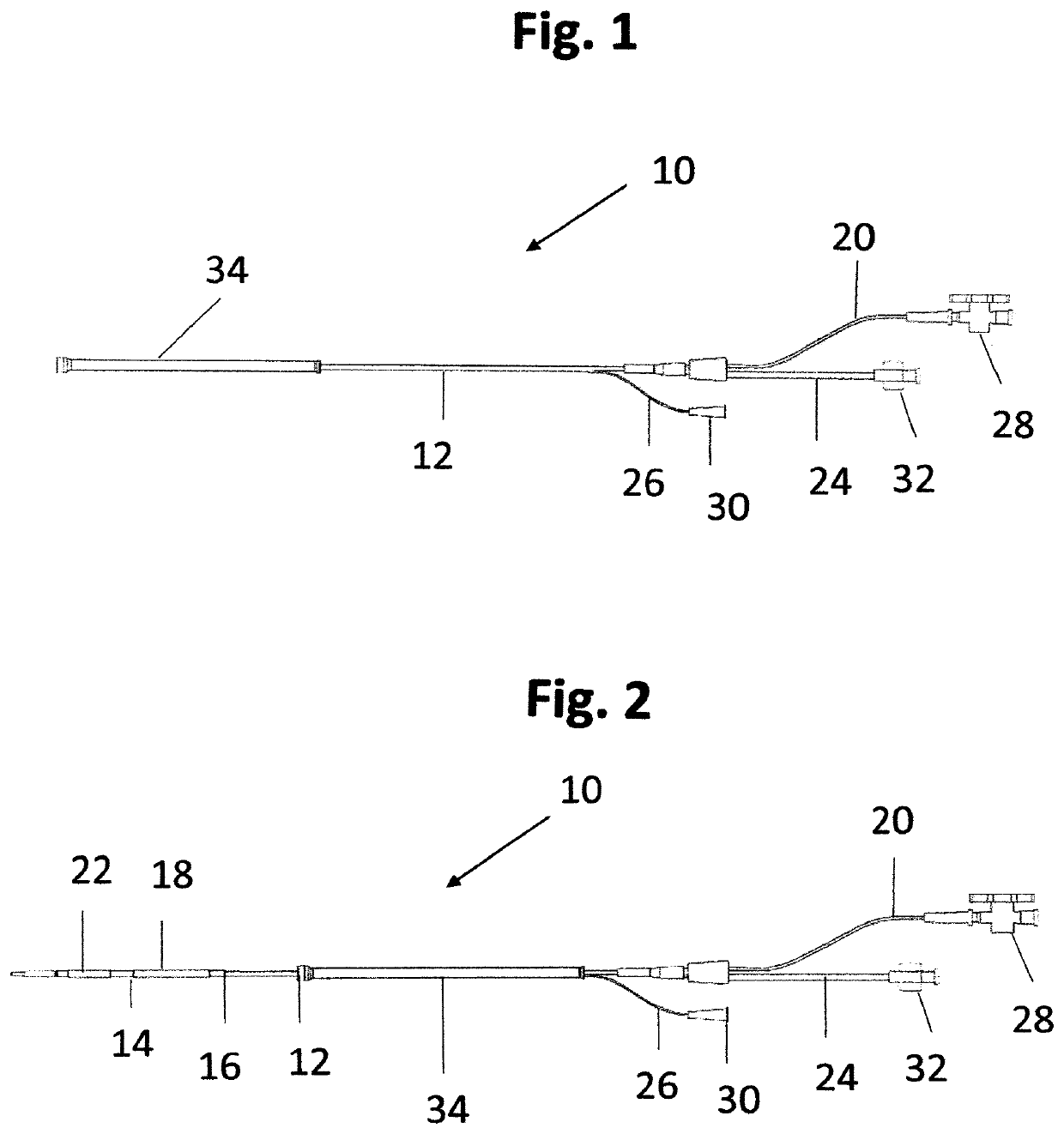
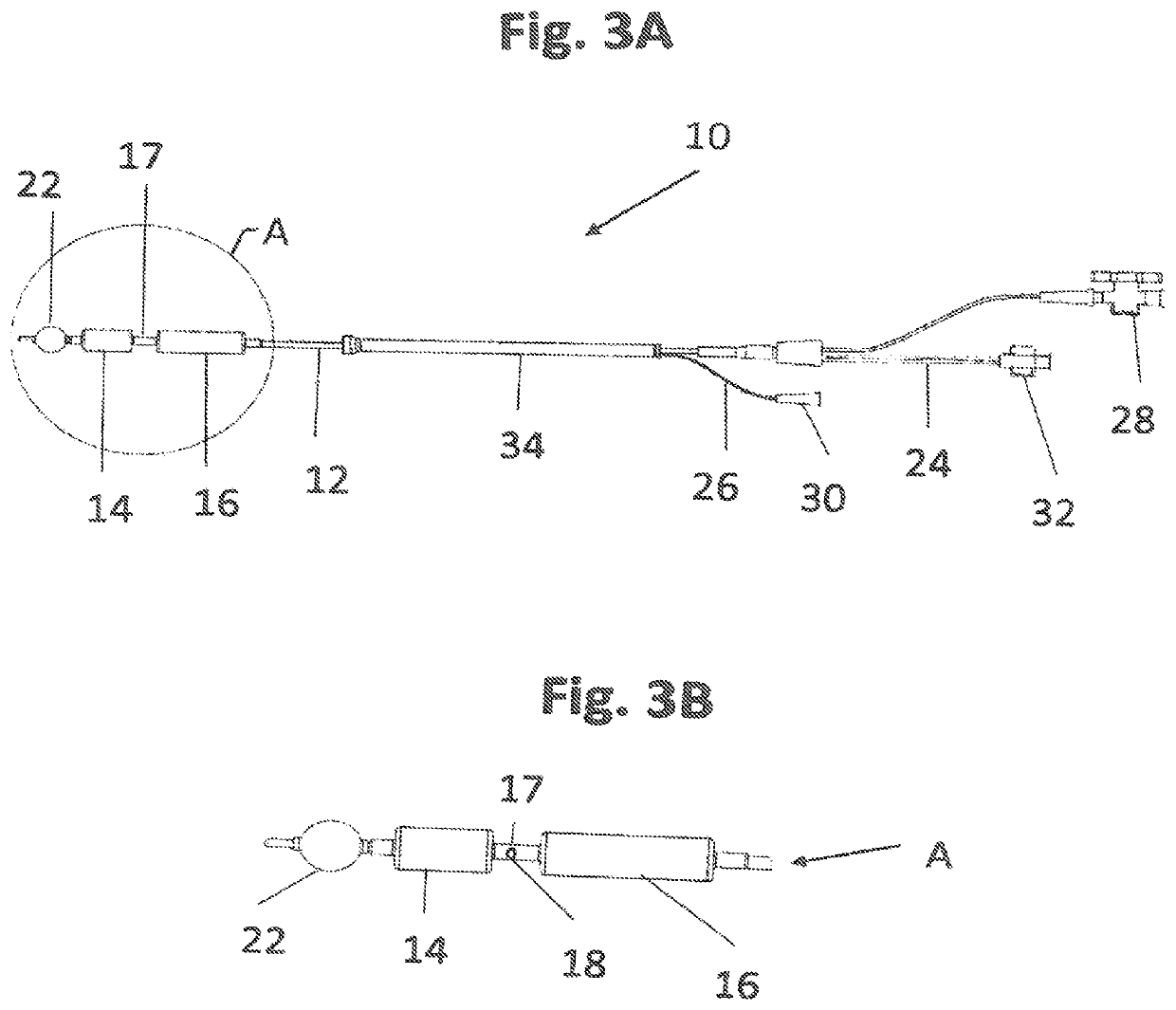
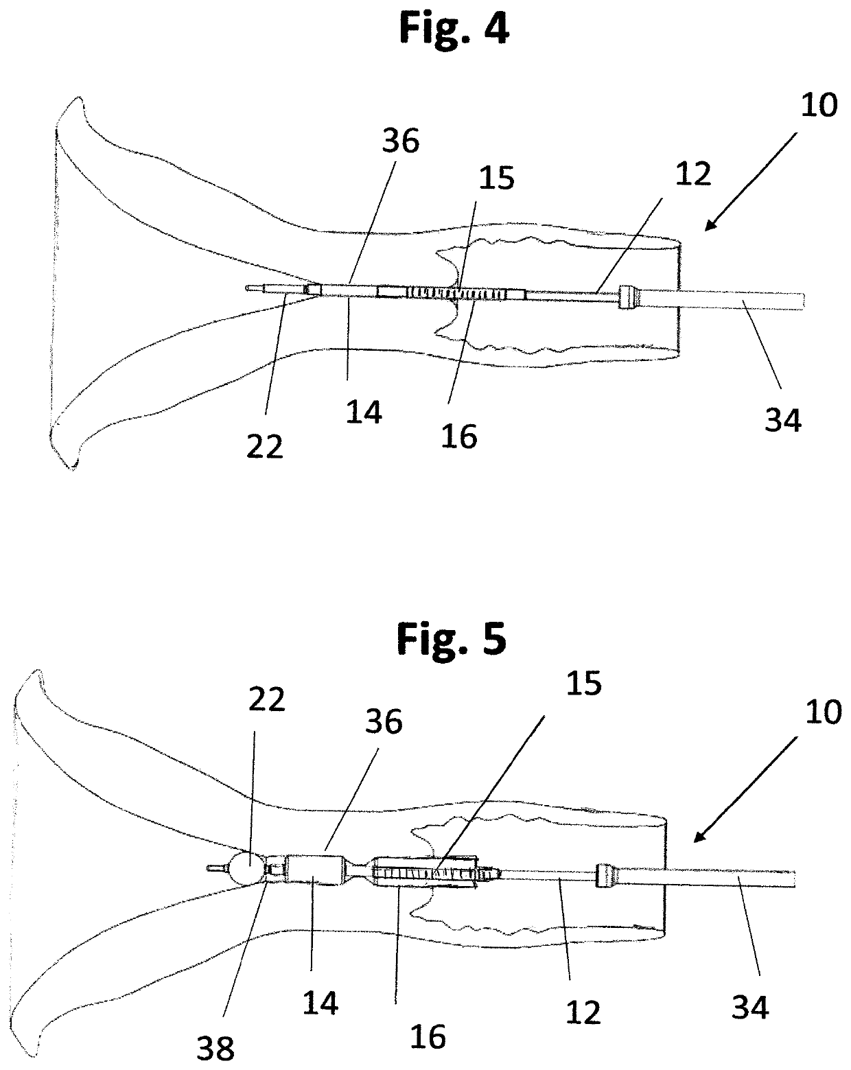
[0024]The procedure of deployment of the cervical canal dilator device of the present invention: The two balloons wrapped around the hollow rod shaft are inflated via the elongated tube and the connection port by pressurized liquid or gas, so as to seal the two orifices (the term “orifice” interchangeably abbreviates to “os”) of the cervical canal (internal os and external os). The third reversibly inflatable balloon is inflated, also using pressurized liquid or gas, inside the uterine cavity via the elongated tube and the connection port. The third balloon is inflated to anchor the hollow rod shaft in the uterine cavity and the cervical canal. A predetermined volume of dilating substance is injected into the cervical canal via the connection port and the elongated tube and through the perforated segment of hollow rod shaft. The dilating substance can have either a liquid or gel characteristics. The dilating substance causes a predetermined dilating width dilation of the cervical canal in correlation with the volume of dilating substance is injected into the cervical canal. The optional graduated markings along the shaft facilitate better control of fine adjustments in the sealing of the cervical canal of the treated patient by the device of the present invention by enabling the exact monitoring of the distances of insertion and withdrawal of the device from the patient.

Problems solved by technology

This process is painful, requires the use of anesthesia, and is associated with a risk of uterine and cervix damage and cervical incompetence.
The mentioned cervix dilating devices are cumbersome to use and do not give the professional operator the ability to readily adjust the procedure to the physiological requirement of any individual treated woman.
Atad's device relates to widening of the cervix canal prior to birth giving and does not relate and is not able to preform controlled cervical canal dilation procedures in treated patients.
Ackerman's device relates to uterus medical treatment procedures and does not relate to and is not able to perform controlled cervical canal dilation procedures in treated patients.

Method used


Image

  • Cervical canal dilation device
  • Cervical canal dilation device
  • Cervical canal dilation device

Examples


Embodiment Construction

[0037]Reference is presently made to the construction of an embodiment of a cervical canal dilation device in accordance to the present invention:

[0038]The cervical canal dilation device (10) of the present invention is constructed of a hollow rod shaft, referred from here after in the text as a “shaft” (12), typically made of (but not limited to) rigid plastic material. The terms “proximal”“distal” in reference to cervical canal dilation device of the present invention relate to the end-side of the shaft that is inserted into the cervix canal when the device is deployed and to the opposite side-end, respectively. In the distal edge-portion of shaft (12) two inflatable dilating balloons, typically, cylinder-shaped (designated: 14 and 16) are wrapped around shaft (12). Optionally, balloon (16) is made of a transparent material, typically but not necessarily, of plastic material. The portion of the hollow shaft wrapped by balloon (16) has graduated markings along the shaft, designated...


PUM


Abstract

The cervical canal dilation device of the present invention relates to controlled injection of liquid or gel to the cervical canal in order to obtain a desired predetermined dilation while causing the treated woman minimal discomfort. The injection of a substance having a liquid or gel characteristics into the cervical canal is done while the inner and outer orifices (internal os and external os) of the canal are sealed by two reversibly inflatable balloons, referred to as the “dilating balloons”. An inflatable balloon at the tip or near the tip of the cervical canal dilation device anchors the device (in the uterine cavity linked to the internal os) to the desired position in the cervix canal for the dilation treatment. The amount of fluid or gel injected into the cervix canal can be calculated apriori to expand the width of the canal to the desired dimension.

Description

FIELD OF THE INVENTION[0001]The present invention relates to a device for performing cervical canal dilations. More specifically, the cervical canal dilation device of the present invention relates to injecting liquid or gel substance to the cervix canal while the canal orifices (internal os and external os) are reversibly sealed, causing a predetermined dilation width.BACKGROUND OF THE INVENTION[0002]The terms “distal” and “proximal” in the context of the present text refer to the direction of the end-portions of the dilation device positioned in the cervix canal in regards to the inner and outer orifices of the cervix canal, respectively.[0003]Approximately 3 million cervical canal dilations are performed annually in the United States for the purpose of intra-uterine procedures. These procedures include: abortions, hysteroscopies and other curettages. Cervical canal dilation allows medical practitioners greater access to the inside of the uterus in order to insert surgical tools f...

Claims


Application Information

Patent Timeline
Patent Type & Authority Patents(United States)
IPC IPC(8): A61M25/10A61M29/02A61M31/00
CPCA61M31/00A61M29/02A61M25/1011A61M2025/1052A61M2025/1015A61M2025/1081A61M2025/0034
Inventor HARPAZ, OMERWEICHSELBAUM, AMNON
Owner AQUEDUCT MEDICAL
Learn More