
Verification module for verifying accuracy of a controller
a verification module and controller technology, applied in the direction of electrical control, testing/monitoring control system, instruments, etc., can solve the problems of insufficient or excessive engine torque, inability to meet the demands of accurate torque, and inability to achieve the verification module b>18/b> of reduced complexity
- Summary
- Abstract
- Description
- Claims
- Application Information
AI Technical Summary
Benefits of technology
Problems solved by technology
Method used
Image

Examples
Embodiment Construction
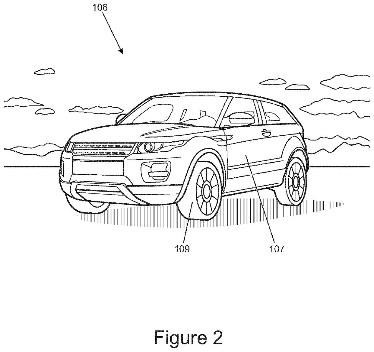
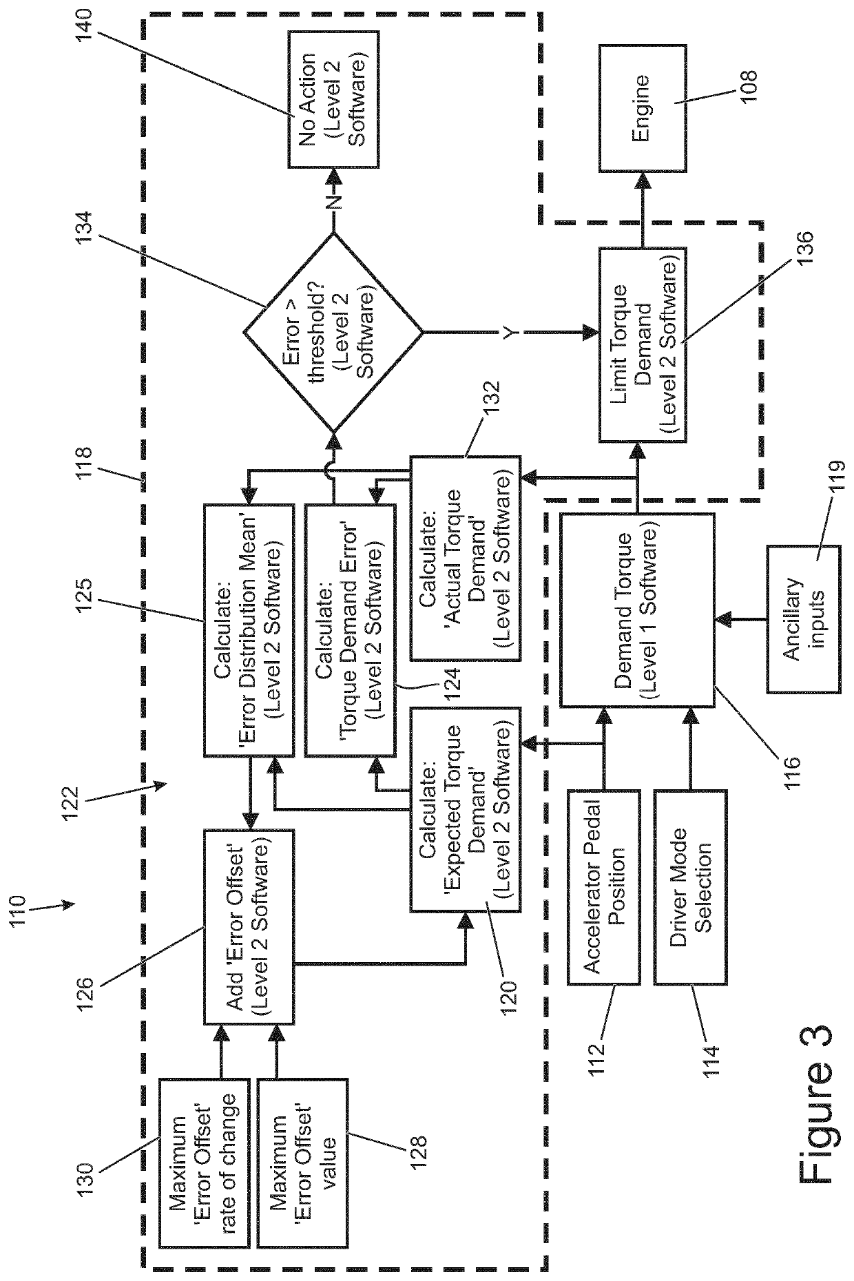
[0042]With reference to FIG. 2, a vehicle 106, such as a car, includes a body 107 and four wheels 109. The wheels 109 are powered by a drive system. The drive system is shown in further details in the form of a block diagram in FIG. 3.
[0043]With reference to FIG. 3, the drive system, or drive-by-wire system 110 (terms to be used interchangeably), includes hardware in the form of an engine 108, an accelerator pedal, and a drive mode selector.
[0044]The accelerator pedal includes a base plate and a pedal part pivotably attached to the base plate. A position sensor using an induction sensor is fixed to the base plate and an activator key is fixed to the pedal. A metallic material, such as mild steel is used to make the activator key. When pivoting the pedal, the activator key is arranged to pass over the induction sensor without contact between the two. The induction sensor outputs a voltage depending on the position of the detected activator key. Ultimately, the position sensor outputs...
PUM
 Abstract
Description
Claims
Application Information