Backlight module and mobile terminal

a backlight module and mobile terminal technology, applied in the field of display, can solve the problems of excessive heat generation of devices, increased thickness of modules, and increased heat generation of backlight devices or converters, so as to reduce heat dissipation costs, and increase the service life of devices

Active Publication Date: 2019-12-24
WUHAN CHINA STAR OPTOELECTRONICS TECH CO LTD
View PDF18 Cites 0 Cited by
  • Summary
  • Abstract
  • Description
  • Claims
  • Application Information

AI Technical Summary

Benefits of technology

[0004]In view of the defects existing in the prior art, the present disclosure provides a backlight module and a mobile terminal which can guarantee good heat dissipation performance on the premise that a thickness of the backlight module is not increased.
[0015]The present disclosure may effectively conduct heat generated by the backlight module to the middle frame of the mobile terminal, and then concentratedly dissipate the heat out, which reduces heat dissipation costs and increases service life of a device at the same time without an obvious increase on a thickness of a module.

Problems solved by technology

With increasingly high ppi (pixels per inch, i.e., a unit of image resolution), luminance is definitely required to be higher and higher, which will then cause the generation of excessive heat from devices such as a backlight device or a converter.
If the heat cannot be dissipated in time, a great hidden trouble will be brought to security and life of a mobile device, and thus, the heat must be dissipated through timely and effective means.
However, considering the limited internal space of the mobile phone, not only cannot a traditional means of attaching a heat dissipation material better dissipate the heat generated inside the module out, but also a thickness of the module will be increased.

Method used


Image

  • Backlight module and mobile terminal

Examples


embodiment 1

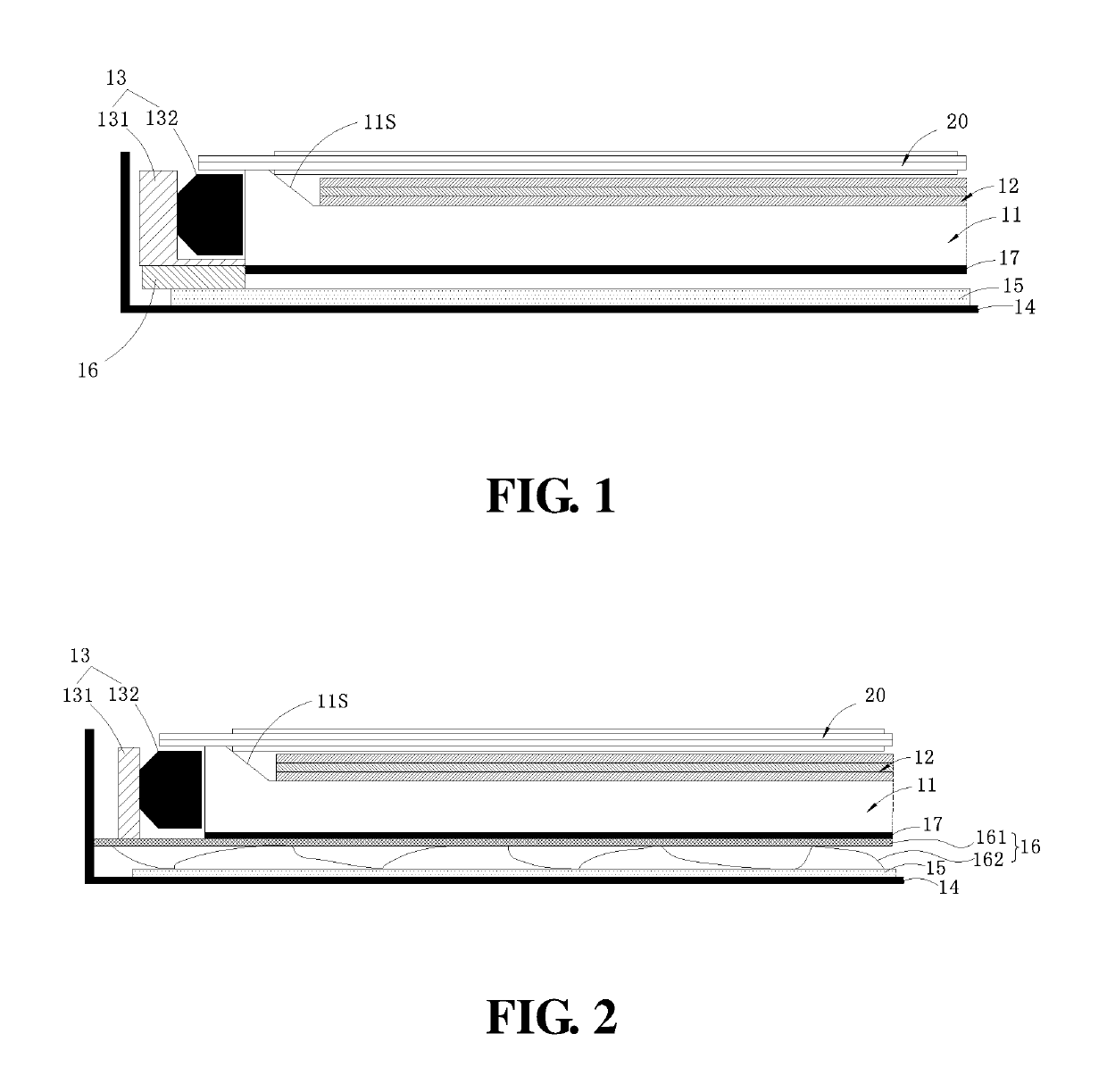
[0021]Referring to FIG. 1, a mobile terminal of the present embodiment includes a backlight module 10 and a display panel 20. The display panel 20 is fixed in an opening of a middle frame 14, and a surface of the display panel 20 may also be covered with a touch screen. The backlight module mainly includes a light guide plate 11, an optical diaphragm group 12 disposed on a light exiting surface of the light guide plate 11, a middle frame 14, a radiating fin 15, a heat conducting connector 16, a backlight source 13 disposed at a light incident end of the light guide plate 11, and a reflective sheet 17 attached on the light guide plate 11 and disposed opposite to the radiating fin 15. The middle frame 14 is disposed on an outer surface of the backlight module and includes a bottom plate and a side wall. The radiating fin 15 is attached to an internal surface of the bottom plate of the middle frame 14, and the heat conducting connector 16 includes a first portion that contacts the back...

embodiment 2

[0025]As illustrated in FIG. 2, different from Embodiment 1, a heat conducting connector 16 of the present embodiment includes a carrying plate 161 and a plurality of spring sheets 162 disposed on a bottom surface of the carrying plate 161. The compressed spring sheets 162 are interposed between the carrying plate 161 and a radiating fin 15, a light guide plate 11 and a backlight source 13 are carried on an upper surface of the carrying plate 161, and the backlight source 13 is attached to one end of the carrying plate 161. The carrying plate 161 may be also used as a flatness holder of the light guide plate 11. The spring sheets 162 are disposed on the carrying plate 161 in an array. When assembling the backlight module 10, a module having metal springs 162 is placed on the radiating fin 15 of a middle frame 14, the compressed springs 162 are nearly completely fitted on the radiating fin 15 to also form a plurality of radiating fins simultaneously, which may improve heat dissipatio...


PUM


Abstract

The present disclosure discloses a backlight module including a light guide plate, an optical diaphragm group disposed on a light exiting surface of the light guide plate, and a backlight source disposed at a light incident end of the light guide plate, a middle frame, a radiating fin and a heat conducting connector. The middle frame is disposed on an outer surface of the backlight module and includes a bottom plate and a side wall. The radiating fin is attached to an internal surface of the bottom plate of the middle frame, and the heat conducting connector includes a first portion that contacts the backlight source and a second portion that only contacts a partial region of the radiating fin. The present disclosure also discloses a mobile terminal.

Description

CROSS-REFERENCES TO RELATED APPLICATIONS[0001]This application is a U.S. national phase application, pursuant to 35 U.S.C. § 371, of PCT / CN2017 / 094324, filed Jul. 25, 2017, designating the United States, which claims priority to Chinese Application No. 201710522151.7, filed Jun. 30, 2017. The entire contents of the aforementioned patent applications are incorporated herein by this reference.TECHNICAL FIELD[0002]The present disclosure relates to the technical field of display, and more particularly, to a backlight module and a mobile terminal.BACKGROUND ART[0003]With the increasing demands for display devices of consumers, the requirements on display techniques also become higher and higher, especially in the aspect of mobile display products such as mobile phones. With increasingly high ppi (pixels per inch, i.e., a unit of image resolution), luminance is definitely required to be higher and higher, which will then cause the generation of excessive heat from devices such as a backli...

Claims


Application Information

Patent Timeline
Patent Type & Authority Patents(United States)
IPC IPC(8): F21V8/00
CPCG02B6/005G02B6/0085G02B6/0088G02B6/002G02B6/0091
Inventor GUO, QINGCHENG, YAN
Owner WUHAN CHINA STAR OPTOELECTRONICS TECH CO LTD
Why Eureka
Try Eureka