Supercharge Your Innovation With Domain-Expert AI Agents!

Apparatus and process for surface treating interior of a workpiece

a technology of interior chamber and apparatus, which is applied in the direction of cleaning hollow objects, manufacturing tools, and using liquids to clean hollow objects, etc., can solve the problems of poor surface quality, difficult or impossible direct communication with the transverse passages from the access opening, and limited accessibility

Active Publication Date: 2019-12-31
CARPENTER STEVEN JAMES
View PDF7 Cites 0 Cited by
  • Summary
  • Abstract
  • Description
  • Claims
  • Application Information

AI Technical Summary

Benefits of technology

The present invention provides a method and apparatus for treating the interior surface of a workpiece by using three nozzles that eject treating material. The first and second nozzles eject the material along parallel lines, and the third nozzle ejects the material perpendicular to the first and second lines. The treating material ejected from the first and second nozzles intersects at a first intersection area, and the material ejected from the third nozzle intervenes with the first and second radial sprays at a second intersection area. This results in a more precise and uniform treatment of the interior surface of the workpiece.

Problems solved by technology

Workpieces and particularly those formed as castings, forgings, fabrications and by machining often have interior chambers formed therein which have only limited accessibility.
Such interior chambers are often shaped and sized so that portions thereof are of significantly larger cross section than any access opening which communicates therewith, and such interior chambers also often include passages or the like which communicate with or project transversely from a main chamber or passage, and as such direct communication with these transverse passages from the access opening is oftentimes difficult or impossible.
This is particularly true when the workpiece is formed as a casting since the core used for defining the interior chamber during the casting process breaks down quickly after pouring and forming of the workpiece, and the material defining the core has to be removed through the access opening, but some material frequently becomes trapped in the interior chamber and / or adheres to the surrounding walls so as to create a poor quality surface.
This technique, however, is relatively ineffective with respect to creating any significant improvement with respect to the smoothness or quality of the boundary walls.
This technique is partially effective for those boundary walls which communicate with and are accessible from the access opening, but is of little value with respect to those walls which are associated with unusual shapes or transversly projecting regions of the interior chamber.
Further, this technique is time consuming and inefficient.
However, the system of this patent does not work with complex interior geometries.

Method used


Image

  • Apparatus and process for surface treating interior of a workpiece
  • Apparatus and process for surface treating interior of a workpiece
  • Apparatus and process for surface treating interior of a workpiece

Examples


Embodiment Construction

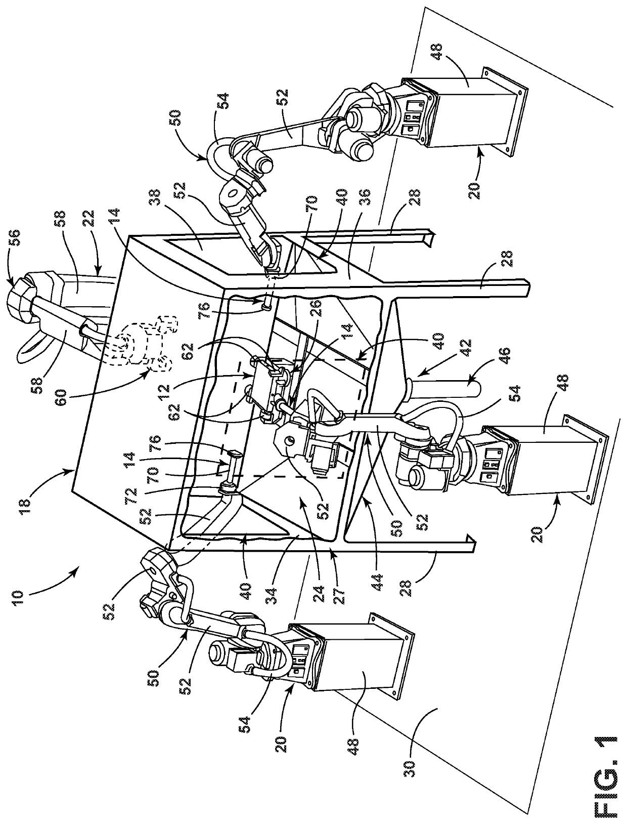
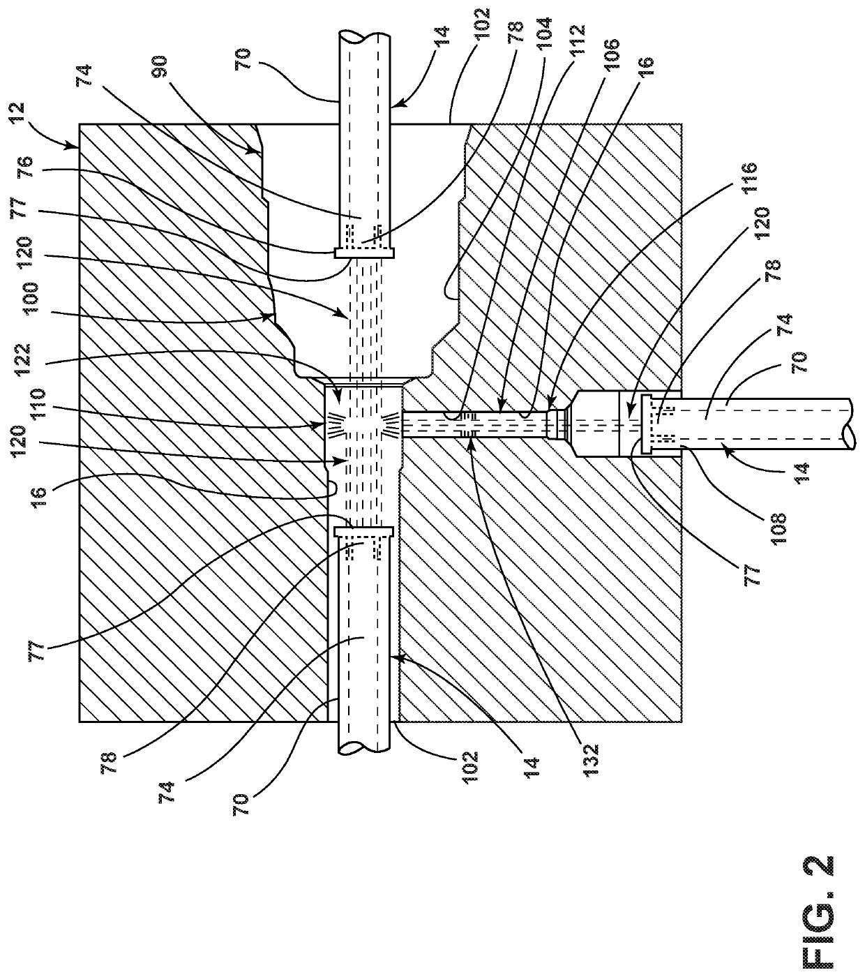
[0012]FIG. 1 illustrates one example of a workpiece treatment station 10 which can be utilized in conjunction with the surface treating apparatus and process disclosed herein. The workpiece treatment station 10 is configured to hold a workpiece 12 while nozzle members 14 are inserted therein to finish interior surfaces 16 (see FIG. 2) of the workpiece 12. While a particular workpiece treatment station 10 is illustrated in FIG. 1, any system that holds the workpiece 12 stationary while the nozzle members 14 are inserted therein can be used. The workpiece can be any workpiece to be treated (e.g., casting, forging, fabrication or one made by machining).

[0013]In the illustrated example, the workpiece treatment station 10 includes a main housing 18, a plurality of nozzle movable arm systems 20 having the nozzle members 14 thereon and surrounding the main housing 18, and a workpiece movable arm system 22 outside the main housing 18 for placing the workpiece 12 into and removing the workpi...


PUM

PropertyMeasurementUnit
velocitiesaaaaaaaaaa
pressureaaaaaaaaaa

Abstract

An apparatus for treating an interior surface of a workpiece comprising at least three nozzles ejecting treating material, with a first one and a second one ejecting the treating material substantially along first and second collinear lines. A third one of the nozzles ejects the treating material substantially along a third line substantially perpendicular to the first and second lines. The treating material ejected from the first one intersects with the treating material ejected from the second one at a first intersection area to radially deflect to form a first radial spray. The treating material ejected from the third one intersects with the first radial spray at a second intersection area to form a second radial spray of treating material. The interior surface of the workpiece adjacent the second intersection area is treated with the treating material of the second radial spray.

Description

FIELD OF THE INVENTION[0001]This invention relates to an apparatus and process for surface treating a boundary wall of an interior chamber associated with a workpiece such as a casting.BACKGROUND OF THE INVENTION[0002]Workpieces and particularly those formed as castings, forgings, fabrications and by machining often have interior chambers formed therein which have only limited accessibility. Such interior chambers are often shaped and sized so that portions thereof are of significantly larger cross section than any access opening which communicates therewith, and such interior chambers also often include passages or the like which communicate with or project transversely from a main chamber or passage, and as such direct communication with these transverse passages from the access opening is oftentimes difficult or impossible. It is usually necessary to attempt to effect at least some treatment of the walls which define the boundary of the interior chamber in an effort to improve th...

Claims


Application Information

Patent Timeline
Patent Type & Authority Patents(United States)
IPC IPC(8): B08B9/057B08B3/02B24C3/04B08B9/00B24C3/32B08B5/02B24C1/08
CPCB08B9/00B08B9/057B24C1/083B24C3/325B08B3/024B24C3/04B08B5/02
Inventor CARPENTER, STEVEN JAMES
Owner CARPENTER STEVEN JAMES
Features
  • R&D
  • Intellectual Property
  • Life Sciences
  • Materials
  • Tech Scout
  • Unparalleled Data Quality
  • Higher Quality Content
  • 60% Fewer Hallucinations
Learn More