Heater device for heating liquefied gas

a heating device and liquefied gas technology, applied in the direction of ohmic resistance waterproof/airtight seals, combustion types, separation processes, etc., can solve the problems of increasing the number of components, the need for higher power, and the inability to atomize liquefied butane, so as to reduce the number of assembling steps and reduce the cost. , the effect of reducing the number of components

Active Publication Date: 2019-12-31
NIPPON THERMOSTAT CO LTD
View PDF22 Cites 2 Cited by
  • Summary
  • Abstract
  • Description
  • Claims
  • Application Information

AI Technical Summary

Benefits of technology

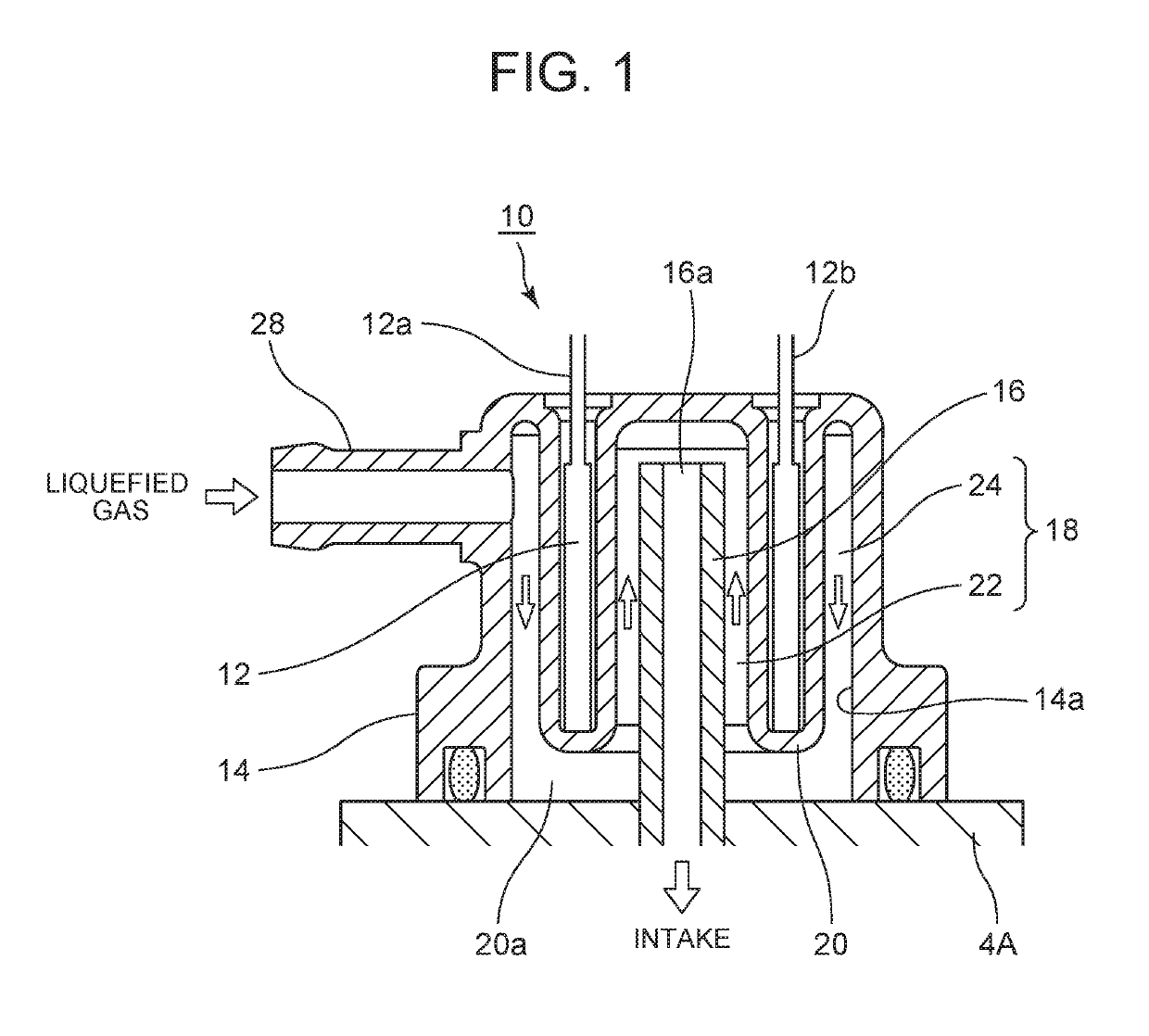
[0033]As described above, according to the heater device for heating liquefied gas pertaining to the present invention, it is configured such that a device housing having a hollow portion including a gas intake pipe projectingly provided to an outer of an instrument body such that liquefied gas is taken in from an outer end, the device housing is attached to an instrument body in a state in which a liquefied gas flow path is formed within the hollow portion and a heater that heats the inside of the hollow portion is built therein, wherein the liquefied gas flow path includes a return flow path formed by folding at least one of an end portion of the flow path inside the hollow portion of the device housing, and thus various superior effects listed below are exhibited.
[0034]1. The vaporizer (liquefied gas evaporator), the piping pipes and the heater device which is provided separately become unnecessary and thus the number of components decreases, the number of assembling steps and costs can be reduced and the entire device can be downsized.2. Although the flow path structure is complicated, since the intake pipe having the gas intake opening is assembled with the device housing and configured to serve as a part of the gas flow path, the number of components and the number of assembling steps can be reduced.[Rule 91 Correction 25.09.2014]3. Further, even when the fluid is a volatile liquefied gas, the airtightness and the safety are improved.4. The flow path distance can be increased while suppressing the overall height of the heater device, the product itself can be downsized and thus it becomes possible to improve layout flexibility.5. The assembly is assembled by assembling the device housing with a built-in heater to the liquefied gas utilization equipment (regulator) and is fixed in place only by bolts, and thus assembly of the complicated flow path structure is easy.
[0035]Further, according to the present invention, in the hollow portion of the device housing, since the partition walls for partitioning the inner side of the hollow portion to be a plurality of flow paths communicating with each other are provided, the following superior effects are exhibited:1, After ensuring the overall size reduction, it is possible to form a return flow path in the hollow portion of the device housing and thus it is possible to efficiently heat the gas fluid using the heater which is built in the housing.
[0036]Further, according to the present invention, the partition walls are, in the hollow portion of the device housing, for example, formed in a cylindrical shape so as to surround the intake pipe at a predetermined interval and the tubular passage, formed on the inner and outer peripheries of the intake pipe, is formed as a return flow path by communicating with the inner end of the heating wall and, further to the partition wall which is cylindrical or the like, by providing either of a planar or cylindrical heater shaped to match the shape of the partition wall, or a plurality of bar-like shaped, a planar or a column-shaped heater that heats the heating wall substantially uniformly, to function as a heating wall, the following superior effects are exhibited.1 Since the overall height of the heater device is reduced, the flow path length is lengthened and the contact surface area with the heater is widened, it is possible to efficiently heat the gas with a small electric power consumption.2 It is possible to securely atomize in a short period of time even at low temperatures.
[0037]Further, according to the heater device for heating liquefied gas pertaining to the present invention includes a cylindrical metal case with the heater built therein and having a tip end thereof closed, wherein the metal case is provided to the device housing so as to extend along an axial direction by inserting into the inner side from an outer end of the intake pipe, wherein a flow path for heating liquefied gas is formed between the cylindrical metal case and an inner wall of the gas intake pipe, and thus the following superior effects are exhibited in addition to the various effects described above.1 Since the heater is placed in the metal case and is extended into the gas intake pipe and the flow path for heating the liquefied gas is formed along thereof, it is possible to more efficiently heat the liquefied gas.2 In particular, since fins are provided along the outer wall of the metal case, heating the liquefied gas passing through the flow path can be carried out more efficiently.

Problems solved by technology

However, according to the configurations as described above, in the liquefied gas utilization equipment system which heats by using the exhaust heat of the exhaust pipe, due to the heat shortage and the necessity of a long period of heating time, it could not atomize liquefied butane especially at low temperatures.
Moreover, in cold regions and at low temperatures such as in winter, in a short flow path, since the transit time and the heating time is short, heating must be carried out at high temperatures and thus higher power was necessary.
Further, the number of components increased and the device was not easy to assemble.
When the fluid was liquid or half solid there was less possibility of ignition but when the liquefied gas was a volatile gas, installation of the heater device 3 between the pipes 2 as conventionally, there were problems in smooth operation, durability and safety.

Method used


Image

  • Heater device for heating liquefied gas
  • Heater device for heating liquefied gas
  • Heater device for heating liquefied gas

Examples


Embodiment Construction

[0045]FIGS. 1 to 4 show an embodiment of a heater device for heating liquefied gas according to the present invention. In the figures, portions that are the same as or corresponding to portions shown in FIG. 7 described above are denoted by the same reference numbers and explanations thereof will be omitted.

[0046]Now, according to the present invention, in a vaporizer serving as liquefied gas-utilization equipment, a heater device 10 for heating liquefied gas that promotes atomization of liquefied gas at low temperatures by heating liquefied gas flowing through a gas flow path is provided. The heater device10 is, in the system shown in FIG. 4, equipped with a device housing 14 having substantially a cup shape with a built-in heater 12 having a cylindrical shape or the like for heating liquefied gas, and when it is assembled to a regulator 4, when having a gas intake opening 16a protruding from the regulator 4 a hollow portion 18 is provided between the device housing 14. The hollow ...


PUM


Abstract

A device housing having a hollow portion including a gas intake pipe projectingly provided to an outer periphery of an instrument body, having a heater built therein and attached to the instrument body. In the hollow portion, a heating wall formed by a bulge extending from the outer end side to the inner end side in the axial direction of the intake pipe and the heater for heating are internally provided. Between the heating wall and a gas intake pipe, and between the heating wall and an inner wall of the housing, inner and outer gas flow paths are formed a liquefied gas introduction side opening is provided at an outer end side of the outer gas flow path, and the outer end side of the inner gas flow path is communicated with a gas intake opening of the tip of the gas intake pipe.

Description

CROSS-REFERENCE TO RELATED APPLICATION[0001]This application is a national phase entry under 35 U.S.C. § 371 of International Application No. PCT / JP2014 / 066133, filed on Jun. 18, 2014, which claims priority to Japanese Patent Application No. 2013-183256, filed on Sep. 4, 2013, the disclosures of which are incorporated herein by reference.TECHNICAL FIELD[0002]The present invention relates to a heater device for heating liquefied gas in liquefied gas-utilization equipment, which promotes atomization of liquefied gas at low temperatures by heating liquefied gas flowing through a gas flow path.BACKGROUND ART[0003]For example, in liquefied gas-utilization equipment such as a generator and the like using cassette gas, a heater device to heat and atomize the liquefied gas is provided. In particular, in this type of utilization equipment, even when the use environment of the equipment is at low temperatures, it is necessary to efficiently heat the liquefied gas and atomize it.[0004]FIG. 7 i...

Claims


Application Information

Patent Timeline
Patent Type & Authority Patents(United States)
IPC IPC(8): F23D11/44F02M21/06F23C9/00F24H1/10H05B3/44H05B3/06F24H9/00
CPCF24H1/102F23D11/44F02M21/06F23C9/00H05B3/44H05B3/06F24H9/0021B01D1/0047F24H1/142F28F2280/06H05B3/04H05B2203/02H05B3/50Y02T10/30
Inventor SATO, YOJISHIMOMURA, KAZUHITO
Owner NIPPON THERMOSTAT CO LTD
Why Eureka
Try Eureka