Reduction of noise interference for fingerprint sensing

a fingerprint sensor and noise interference technology, applied in the field of fingerprint sensor noise reduction, can solve the problems of occupying space, generating inaccurate fingerprint sensor sensing, incurring extra cost, etc., and achieve the effect of reducing noise interference and eliminating nois

Active Publication Date: 2019-12-31
IMAGE MATCH DESIGN
View PDF2 Cites 20 Cited by
  • Summary
  • Abstract
  • Description
  • Claims
  • Application Information

AI Technical Summary

Benefits of technology

[0006]One objective of the present invention is to provide circuit and method by which noise interference in a fingerprint sensor is reduced.
[0009]Taking advantages of the phenomenon that two adjacent sensing plates are susceptible to a same noise at a same time point, the present invention subtracts the first sensing data from the second sensing data (which two sets of sensing data are detected at a same time point) to obtain a noise-free difference so that, once a noise-free first fingerprint data corresponding to the fingerprint portion on the first sensing plate is obtained, a noise-free second fingerprint data corresponding to the fingerprint portion on the second sensing plate can be determined by calculation, and by doing so, the present invention reduces noise interference effectively. The first fingerprint data can be obtained by eliminating noise from the first sensing data, or preset reference values can be used as the first fingerprint data. Once the second fingerprint data is obtained, the foregoing steps can be repeated to obtain third fingerprint data, which corresponds to the fingerprint portion on a third sensing plate that is adjacent to the second sensing plate.

Problems solved by technology

While detecting fingerprints, a fingerprint sensor may generate inaccurate sensing results due to noise in the power source or in the environment.
However, the use of a common ground plate requires additional steps in the sensor manufacturing process, incurs extra cost, and takes up certain space.
This is why common ground plates are no longer suitable for use when the volume of circuits is gradually reduced.
U.S. Pat. No. 7,460,697 reduces noise interference by adding more sensing plates, but this approach is costly and complicates the sensor manufacturing process even more.
U.S. Pat. No. 8,787,632 reduces noise interference by sensing fingerprints while noise is relatively low, but the avoidance of noise prolongs the sensing time.
U.S. Pat. No. 4,811,414 uses an averaging method to reduce noise interference, and yet the fluctuation of noise over time makes it impossible to reduce noise interference effectively.
It has also been proposed to eliminate the noise in the sensing data of each sensing plate by an oversampling or averaging method, but the sensing time required to obtain fingerprint data from all the sensing plates will be exceedingly long.

Method used


Image

  • Reduction of noise interference for fingerprint sensing
  • Reduction of noise interference for fingerprint sensing
  • Reduction of noise interference for fingerprint sensing

Examples


first embodiment

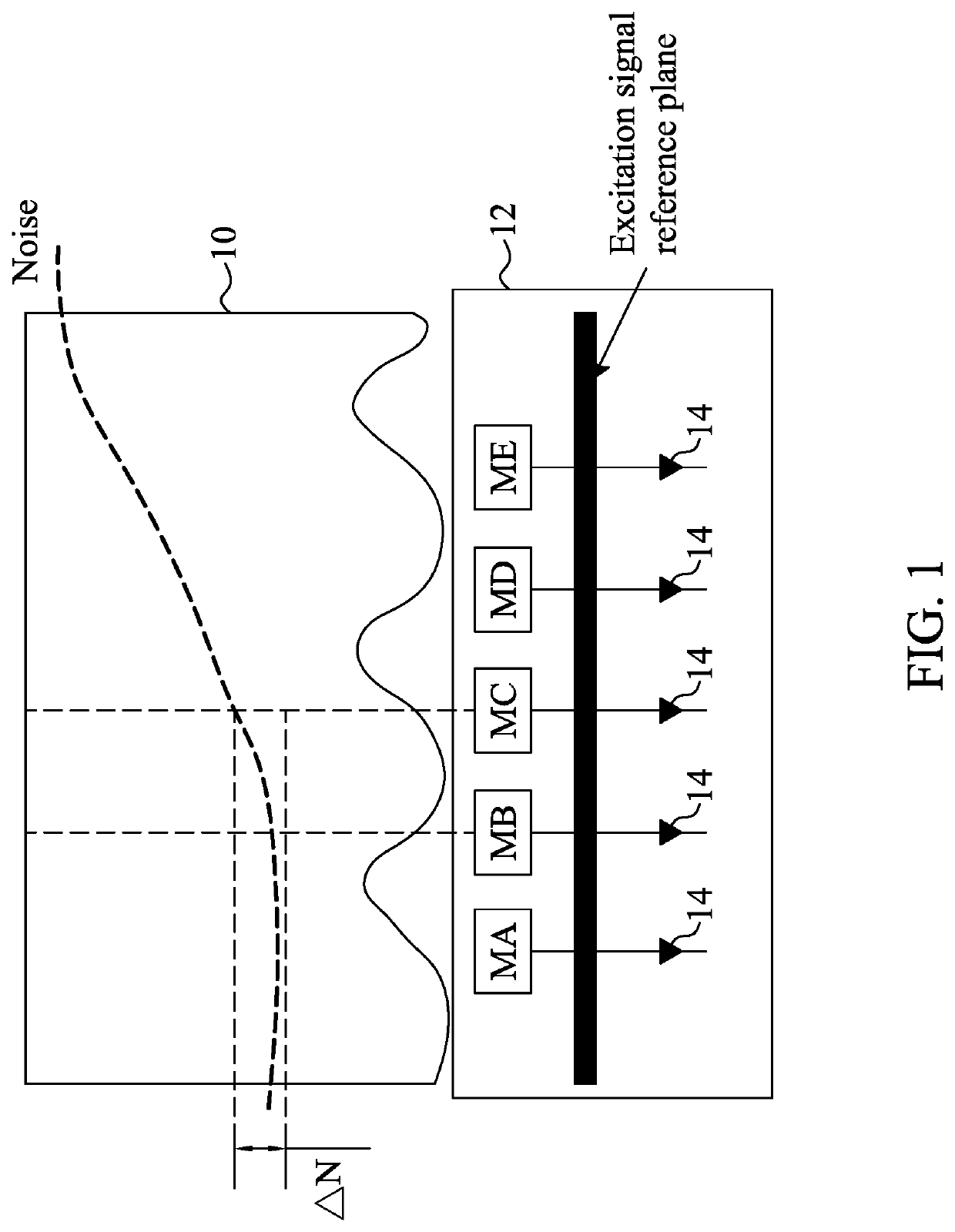
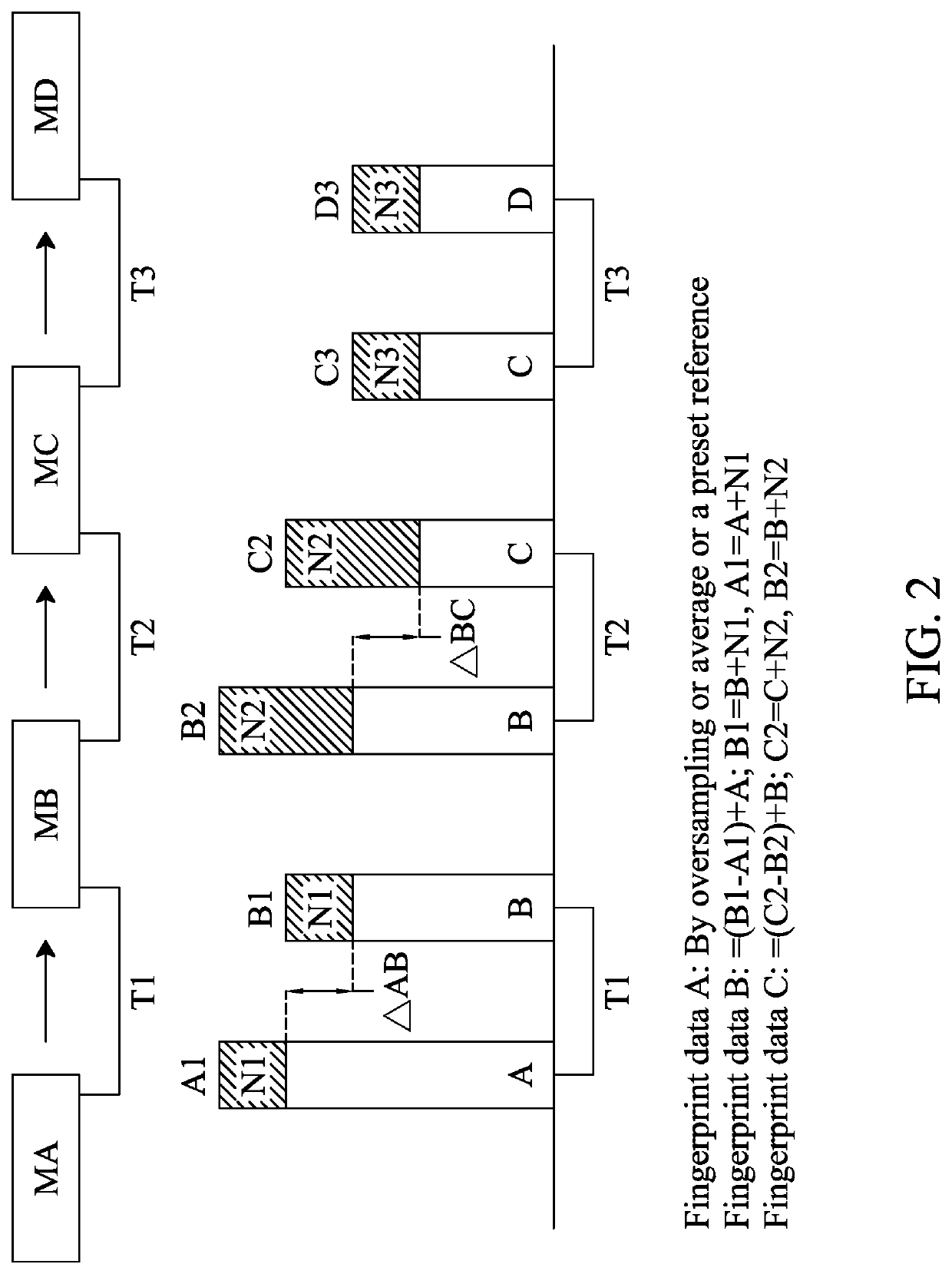
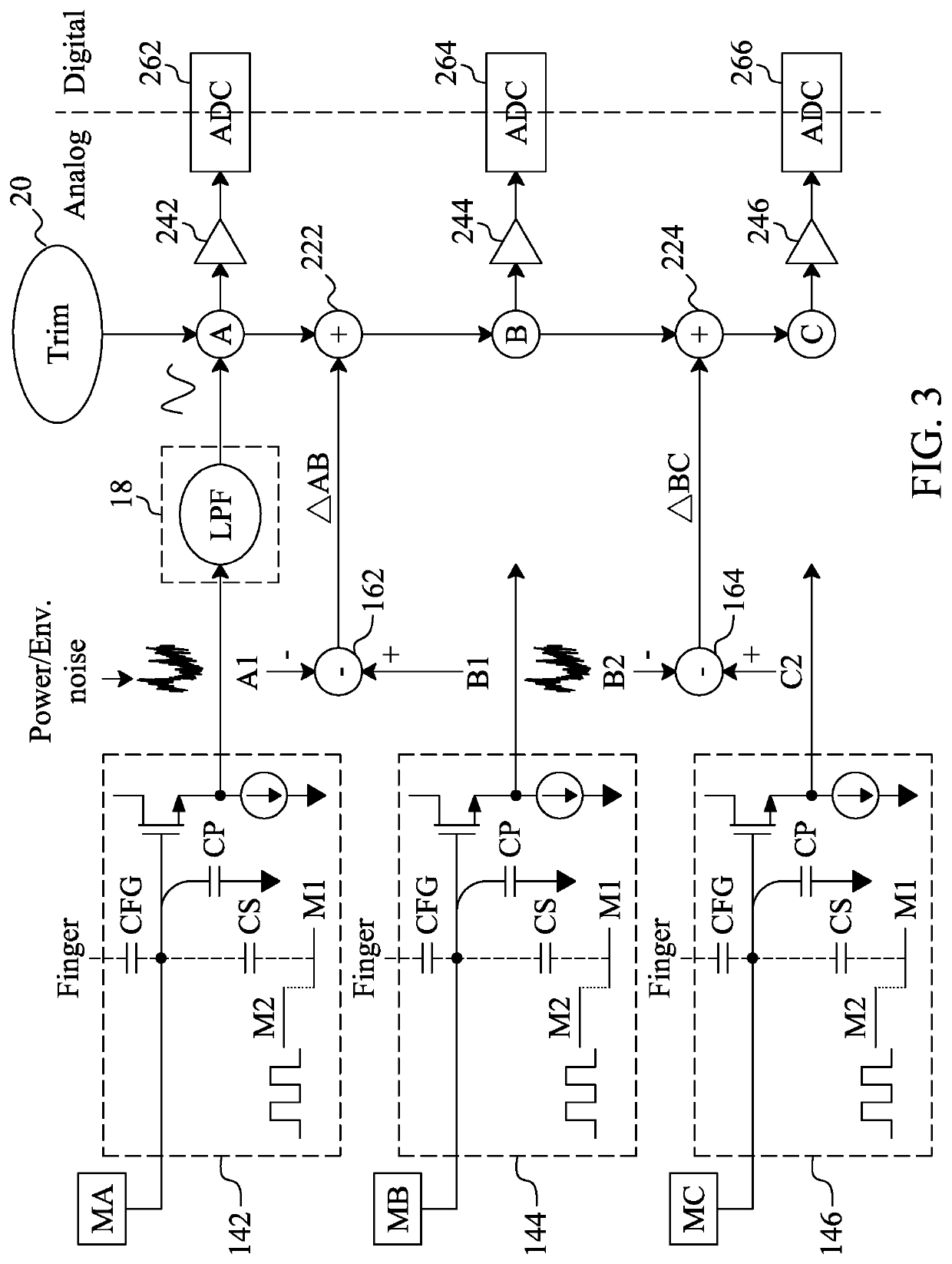
[0020]Please refer to FIG. 2 for an illustration of the principle of the present invention and FIG. 3 for the fingerprint sensor 12 according to the present invention. A first sensing circuit 142 and a second sensing circuit 144 detect a first sensing plate MA and a second sensing plate MB, respectively, at a same time point T1, to obtain first sensing data A1 of the first sensing plate MA and second sensing data B1 of the second sensing plate MB, wherein the first and the second sensing circuits 142 and 144 are connected to the first and the second sensing plates MA and MB respectively. As the first sensing plate MA and the second sensing plate MB are adjacent to each other, the first sensing data A1 and the second sensing data B1 have a same noise. As shown in FIG. 2, the first sensing data A1 includes first fingerprint data A and noise N1, and the second sensing data B1 includes second fingerprint data B and the same noise N1. The subtractor 162 subtracts the first sensing data A...

second embodiment

[0024]FIG. 4 shows the fingerprint sensor 12. The circuitry in this embodiment is identical to that in FIG. 3 except that the buffers 242 and 244 in FIG. 4 are connected to the sensing circuits 142 and 144 respectively, and that therefore the sensing data A1 and B1 output respectively from the sensing circuits 142 and 144 will go through the buffers 242 and 244 respectively before noise elimination (i.e., the subtraction and addition operations).

third embodiment

[0025]FIG. 5 shows the fingerprint sensor 12. The circuitry in this embodiment is different from that in FIG. 3 in that the fingerprint sensor in FIG. 5 uses a digital circuit to perform subtraction and addition for noise elimination. In FIG. 5, the first sensing data A1 detected by the first sensing circuit 142 goes through the noise elimination circuit 18 to have noise filtered out and thereby generate the first fingerprint data A. The first fingerprint data A is then fed through the buffer 242 into the ADC 262, in order for the ADC 262 to convert the first fingerprint data A into the digital first fingerprint data A_d, and for the digital adjustment circuit 32 to adjust the digital first fingerprint data A_d as needed. More specifically, the first sensing circuit 142 and the second sensing circuit 144 sense the adjacent sensing plates MA and MB respectively at the same time to generate the first sensing data A1 of the sensing plate MA and the second sensing data B1 of the sensing...


PUM


Abstract

In a fingerprint sensor, two adjacent sensing plates are detected at a same time to obtain first sensing data and second sensing data therefrom respectively, so that the first sensing data and the second sensing data include a same noise, then the first sensing data is subtracted from the second sensing data to generate a difference by which the noise is eliminated, and the difference is added to first fingerprint data corresponding to the sensing plate which provides the first sensing data, resulting in second fingerprint data corresponding to the other sensing plate. The fingerprint portions on the two adjacent sensing plates are determined according to the first and the second fingerprint data respectively.

Description

CROSS-REFERENCE TO RELATED APPLICATIONS[0001]This application claims the priority benefit of Taiwan Application No. 106111365, filed 5 Apr. 2017, the contents of which in its entirety are herein incorporated by reference.FIELD OF THE INVENTION[0002]The present invention generally relates to circuit and method for fingerprint sensing and, more particularly, to reduction of noise interference for fingerprint sensing.BACKGROUND OF THE INVENTION[0003]While detecting fingerprints, a fingerprint sensor may generate inaccurate sensing results due to noise in the power source or in the environment. To reduce such noise interference, many methods can be used nowadays. For example, the circuits in a fingerprint sensor and the finger whose fingerprint is to be sensed can be provided with the same ground potential by a common ground plate in order to eliminate some of the noise. However, the use of a common ground plate requires additional steps in the sensor manufacturing process, incurs extra...

Claims


Application Information

Patent Timeline
Patent Type & Authority Patents(United States)
IPC IPC(8): G06K9/00G06K9/28G06K9/40G06V40/13G06V10/30G06V30/144
CPCG06K9/00026G06K9/40G06K9/28G06K9/00013G06K9/0002G06V40/12G06V40/13G06V10/30G06V40/1306G06V30/144G06V40/1335
Inventor YAN, YEHSUAN
Owner IMAGE MATCH DESIGN
Why Eureka
Try Eureka