Method of and apparatus for controlling vehicle braking

Active Publication Date: 2020-01-28
BLUE LEAF I P
View PDF14 Cites 0 Cited by
  • Summary
  • Abstract
  • Description
  • Claims
  • Application Information

AI Technical Summary

Benefits of technology

[0020]Conveniently the maximum braking power signal is such as to give rise to a constant or approximately constant value of braking power applied by the SAHR brake. This advantageously ensures that the cooling capacity of the SAHR brake is not exceeded.
[0021]The mathematical basis of

Problems solved by technology

This in turn reduces the risk of damage to the SAHR

Method used


Image

  • Method of and apparatus for controlling vehicle braking
  • Method of and apparatus for controlling vehicle braking

Examples


Example

DETAILED DESCRIPTION OF THE DRAWINGS

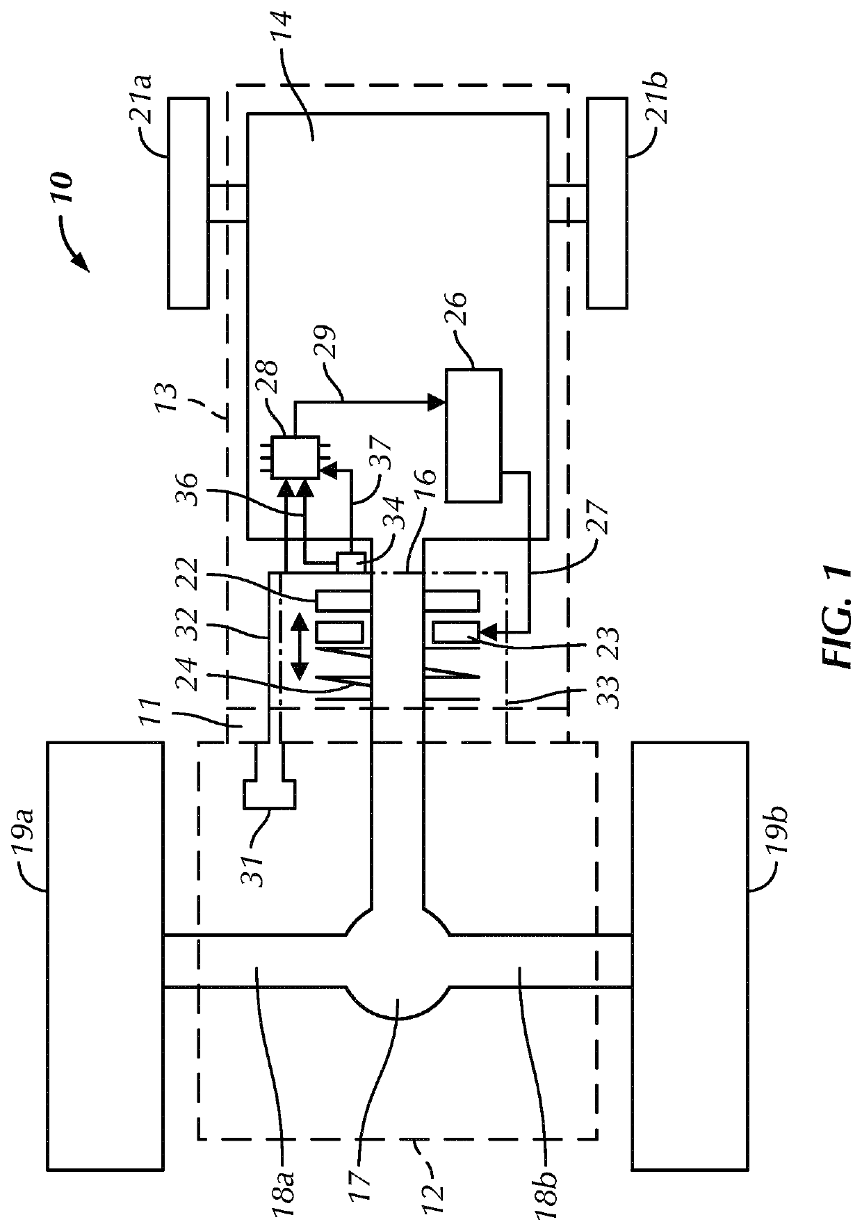
[0036]Referring to the drawings there is shown in schematic, plan view form a vehicle 10 according to the invention. Vehicle 10 in Figure is a tractor, although this need not be the case and the vehicle may be any of the kinds mentioned herein. As is well known a tractor includes many more parts than those shown in FIG. 1, which illustrates only the features of a tractor that are needed for an understanding of the invention.

[0037]To this end tractor 10 of FIG. 1 includes a vehicle frame 11 supporting a driver's cab 12, engine hood 13, and an engine 14 (that in virtually all cases is a diesel engine) connected to drive a drive train described in more detail below.

[0038]The primary components of the engine 14 and connected drive train are well known to the person of skill in the art and do not need to be described herein. Thus FIG. 1 omits conventional features of a vehicle drive train such as a fueling system, governor or throttle control, variable...


PUM


Abstract

A method of controlling deceleration of a vehicle which includes the steps of sensing the speed of rotation of the output shaft and generating an output shaft speed signal. The method also includes deriving from the output shaft speed signal a deceleration signal indicative of deceleration of the vehicle, and generating in accordance with a selectively effective feedback control scheme a braking command. The method further includes using the output shaft speed signal to calculate a maximum braking power signal and modulating the braking command in dependence on the maximum braking power signal in order to limit the braking power applied in the SAHR brake. The maximum braking power signal is determined in dependence on the heat dissipating capacity of the SAHR brake and is such as to give rise to a constant or approximately constant value of braking power dissipated in the SAHR brake.

Description

BACKGROUND OF THE INVENTION[0001]The invention relates to a powered land vehicle including at least one spring-applied hydraulic release (SAHR) vehicle brake.[0002]In such a brake first and second brake elements, mounted respectively on a rotatable part of the drive train of the vehicle such as a powered output shaft and a fixed part such as the vehicle frame are moveable between mutually engaged and separated configurations.[0003]In the separated configuration the rotatable component is free to rotate, thereby permitting the transmission of drive from e.g. a diesel engine forming part of the vehicle to a ground-engaging member such as a wheel including a tyre. In the mutually engaged configuration the second element brakes rotation of the rotatable part supporting the first brake element with the result that the transmission of drive is resisted or prevented and therefore the vehicle as a whole is braked.[0004]In almost all cases the second brake element is moveable towards and awa...

Claims


Application Information

Patent Timeline
IPC IPC(8): B60T13/22B60W10/196B60T1/06
CPCB60T13/22B60W10/196B60T1/065B60T1/062
Inventor MORANDI, GABRIELE
Owner BLUE LEAF I P
Why Eureka
Try Eureka