
Power supply apparatus and image forming apparatus

a technology of power supply apparatus and image forming apparatus, which is applied in the direction of electric variable regulation, process and machine control, instruments, etc., can solve the problems of not taking into account the correction of the intercept of the function, the increase of output voltage variation, and the increase of output voltage ripple. , to achieve the effect of improving the responsivity of output voltage and reducing the ripple of output voltag

Active Publication Date: 2020-01-28
CANON KK
View PDF16 Cites 0 Cited by
  • Summary
  • Abstract
  • Description
  • Claims
  • Application Information

AI Technical Summary

Benefits of technology

[0006]An aspect of the present invention is an inexpensive and small-sized power supply apparatus that achieves both the improvement of responsivity of output voltage and the reduction of ripple of the output voltage within the range of ratings of input voltage.
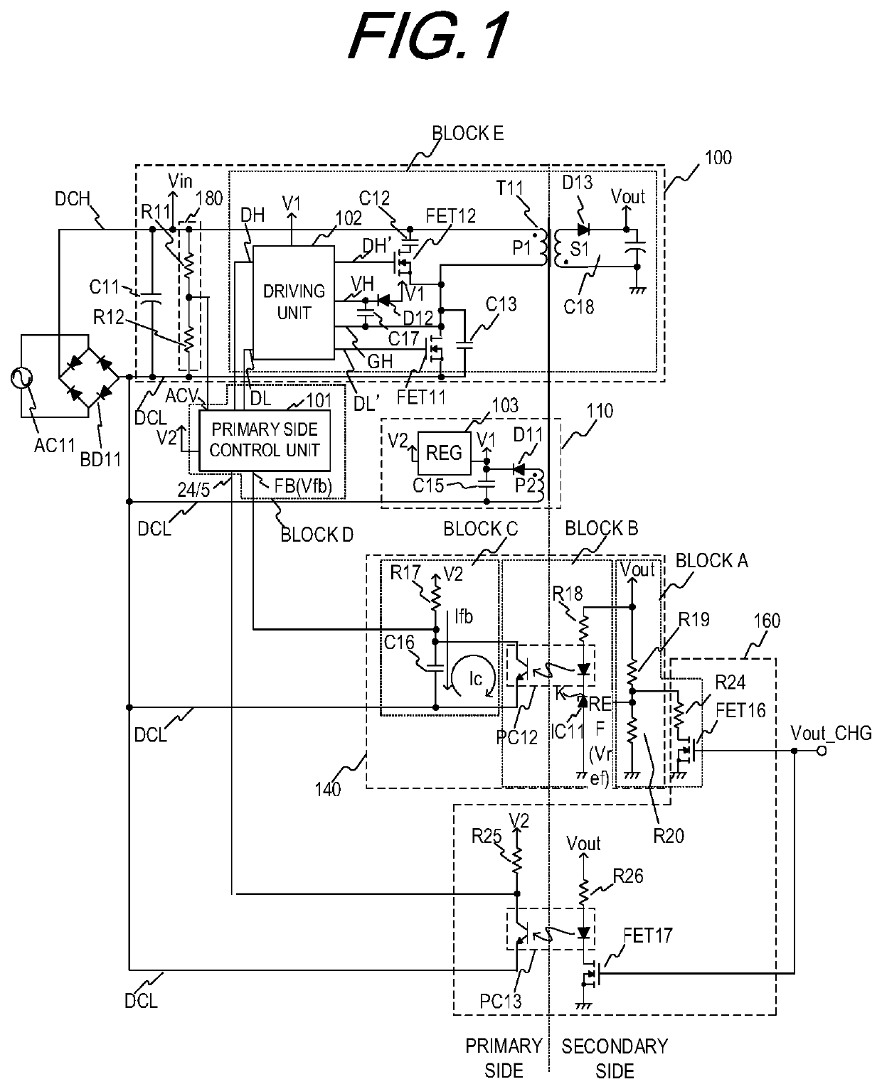
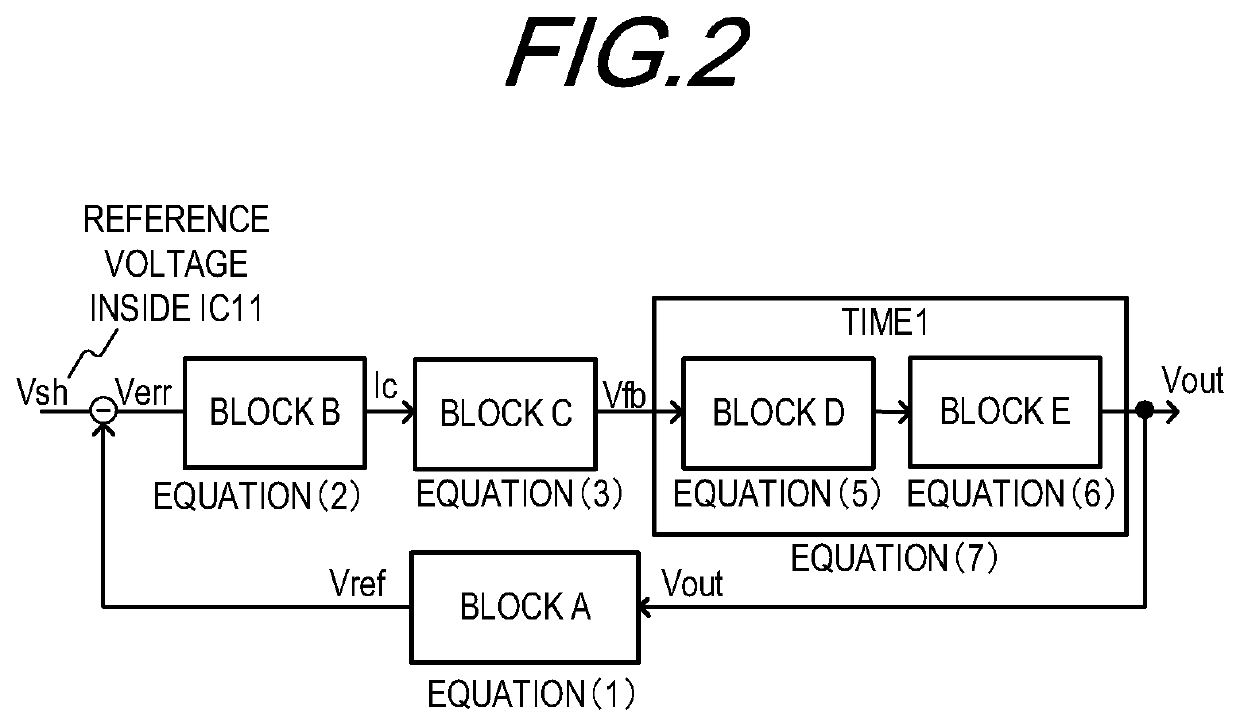
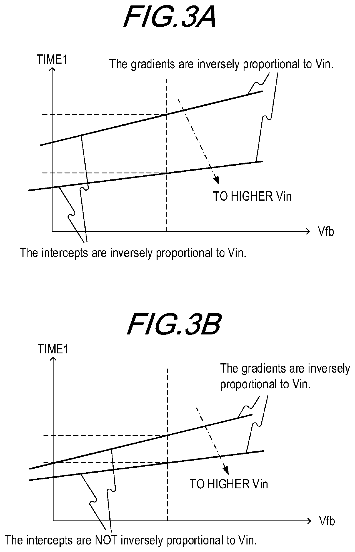
[0007]Another aspect of the present invention is a power supply apparatus including a transformer configured to isolate a primary side and a secondary side, a switching unit provided on the primary side of the transformer and configured to perform switching operation for converting an input voltage in which an AC voltage are rectified and smoothed and outputting an output voltage from the secondary side of the transformer, a first detection unit configured to detect the output voltage, a feedback unit configured to generate a feedback voltage based on the voltage detected by the first detection unit; a control unit configured to control the switching operation of the switching unit based on the feedback voltage generated by the feedback unit; and a second detection unit configured to detect the AC voltage. The control unit performs the switching operation such that the higher the AC voltage detected by the second detection unit, the shorter a conduction time period of the switching unit corresponding to the feedback voltage and the smaller a variation amount of the conduction time period of the switching unit corresponding to a variation amount of the feedback voltage.
[0008]A further aspect of the present invention is an image forming apparatus including: an image forming unit for forming an image, and a power supply apparatus configured to power the image forming apparatus, wherein the power supply apparatus includes: a transformer configured to isolate a primary side and a secondary side, a switching unit provided on the primary side of the transformer and configured to perform switching operation for converting an input voltage in which an AC voltage are rectified and smoothed and outputting an output voltage from the secondary side of the transformer, a first detection unit configured to detect the output voltage; a feedback unit configured to generate a feedback voltage based on the voltage detected by the first detection unit; a control unit configured to control the switching operation of the switching unit based on the feedback voltage generated by the feedback unit; and a second detection unit configured to detect the AC voltage. The control unit performs the switching operation such that the higher the AC voltage detected by the second detection unit, the shorter a conduction time period of the switching unit corresponding to the feedback voltage and the smaller a variation amount of the conduction time period of the switching unit corresponding to a variation amount of the feedback voltage.

Problems solved by technology

Therefore, it is often the case that a lower input voltage causes lower responsivity of the output voltage, resulting in an increase in the output voltage variation due to load variation, while a higher input voltage causes greater ripple of the output voltage.
However, correction of the intercept of the function is not taken into account.
The power supply apparatus is thus affected by the input voltage, and this may lead to the difficulty in achievement of both the responsivity of the output voltage and the improvement of ripple of the output voltage, and to increased evaluation man-hours in designing.

Method used


Image

  • Power supply apparatus and image forming apparatus
  • Power supply apparatus and image forming apparatus
  • Power supply apparatus and image forming apparatus

Examples


first embodiment

[0026]When a high-level Vout CHG signal is output, the FET16 is turned on to cause the resistors R20 and R24 to be connected in parallel. This changes the voltage division ratio of the voltage input to the REF terminal of the shunt regulator IC11 to the power supply voltage Vout, resulting in a change in the target voltage of the power supply voltage Vout. Compared with the case where the low-level Vout CHG signal is output, the target voltage of the power supply voltage Vout increases. In the first embodiment, it is assumed that the target voltage of the power supply voltage Vout is 5 V for the low-level Vout CHG signal, and 24 V for the high-level Vout CHG signal. When the high-level Vout CHG signal is output, the FET17 is also turned on. Since current flows from the power supply voltage Vout to the diode of the photocoupler PC13 via a resistor R26, current also flows from the power supply voltage V2 to the transistor of the photocoupler PC13 via the resistor R25. Thus, a low-leve...

second embodiment

[0066]Thus, an inexpensive and small-sized power supply apparatus can be realized that achieves both the improvement of responsivity of output voltage and the reduction of ripple of the output voltage within the range of ratings of input voltage.

[0067]The power supply apparatus described in the first and second embodiments are applicable, for example, as a low-voltage power supply in an image forming apparatus, i.e., as a power supply that powers a controller (a control unit) and driving units such as motors. Described below is a configuration of an image forming apparatus to which the power supply apparatus in the first and second embodiment is applied.

[0068][Configuration of Image Forming Apparatus]

[0069]As an exemplary image forming apparatus, a laser beam printer will be described. FIG. 5 illustrates a schematic configuration of a laser beam printer as an example of electrophotographic printers. The laser beam printer 300 includes: a photosensitive drum 311 as an image bearing ...

third embodiment

[0072]Thus, an inexpensive and small-sized power supply apparatus can be realized that achieves both the improvement of responsivity of output voltage and the reduction of ripple of the output voltage within the range of ratings of input voltage.


PUM


Abstract

The power supply apparatus includes a transformer, a switching unit provided on a primary side of the transformer and configured to perform switching operation for converting an input voltage resulting from rectification and smoothing of an AC voltage and outputting an output voltage from a secondary side of the transformer; a first detection unit configured to detect the output voltage, a feedback unit configured to generate a feedback voltage based on the voltage detected by the first detection unit; a control unit configured to control the switching operation of the switching unit based on the feedback voltage generated by the feedback unit; and a second detection unit configured to detect the AC voltage.

Description

BACKGROUND OF THE INVENTIONField of the Invention[0001]The present invention relates to a power supply apparatus and an image forming apparatus, and more particularly to a control technique for minimizing increases in cost and size of the power supply apparatus.Description of the Related Art[0002]A power supply apparatus typically determines the conduction time period or ON-duty of a switching element according to a voltage (hereinafter referred to as a feedback voltage) obtained via a feedback unit from an output voltage. The conduction time period or ON-duty required for achieving a necessary output voltage is shorter as an AC voltage (an input voltage) of a commercial AC power supply is lower, and is longer as the input voltage is higher. Therefore, it is often the case that a lower input voltage causes lower responsivity of the output voltage, resulting in an increase in the output voltage variation due to load variation, while a higher input voltage causes greater ripple of the...

Claims


Application Information

Patent Timeline
Patent Type & Authority Patents(United States)
IPC IPC(8): H02M3/335H04N1/00H02M1/00
CPCH02M3/33507H02M3/33523H02M2001/0022H04N1/00888H02M1/4258H02M7/2176H02M1/0025Y02B70/10H02M7/00H02M1/0022
Inventor ASANO, HIROKISHIMURA, YASUHIRO
Owner CANON KK
Learn More