
Sensor device for electrical impedance tomography imaging, electrical impedance tomography imaging instrument and electrical impedance tomography method

a technology of electrical impedance tomography and sensor device, which is applied in the field of sensor device for electrical impedance tomography, electrical impedance tomography imaging instrument and electrical impedance tomography method, can solve the problems of too late and entail risks in lung recruitment manoeuvres, and achieve the effects of monitoring lung function, improving reference images, and improving utility and usability of eit technology

Active Publication Date: 2020-02-04
SWISSTOM
View PDF19 Cites 1 Cited by
  • Summary
  • Abstract
  • Description
  • Claims
  • Application Information

AI Technical Summary

Benefits of technology

[0023]Therefore, it is an advantage of the present invention to provide a device and a method that is able to measure and compute reliable EIT difference images. It is another advantage to provide a device and method that allows one to monitor lung function accurately and in real time. Furthermore, it is an advantage to create improved reference images and to improve utility and usability of EIT technology. Moreover, it is an advantage to improve regularization methods.
[0024]Above advantages are achieved by providing and using spatial information in order to create improved EIT images. Spatial information comprises data describing body position and / or orientation, i.e. the spatial orientation of the body or a body part. For example standard regularization methods are extended by integrating spatial information, i.e. information about orientation and position of a body part, such as e.g. the thorax, during EIT analysis.
[0025]In detail, above advantages are achieved with an inventive sensor device, an inventive EIT imaging instrument and an EIT imaging method.
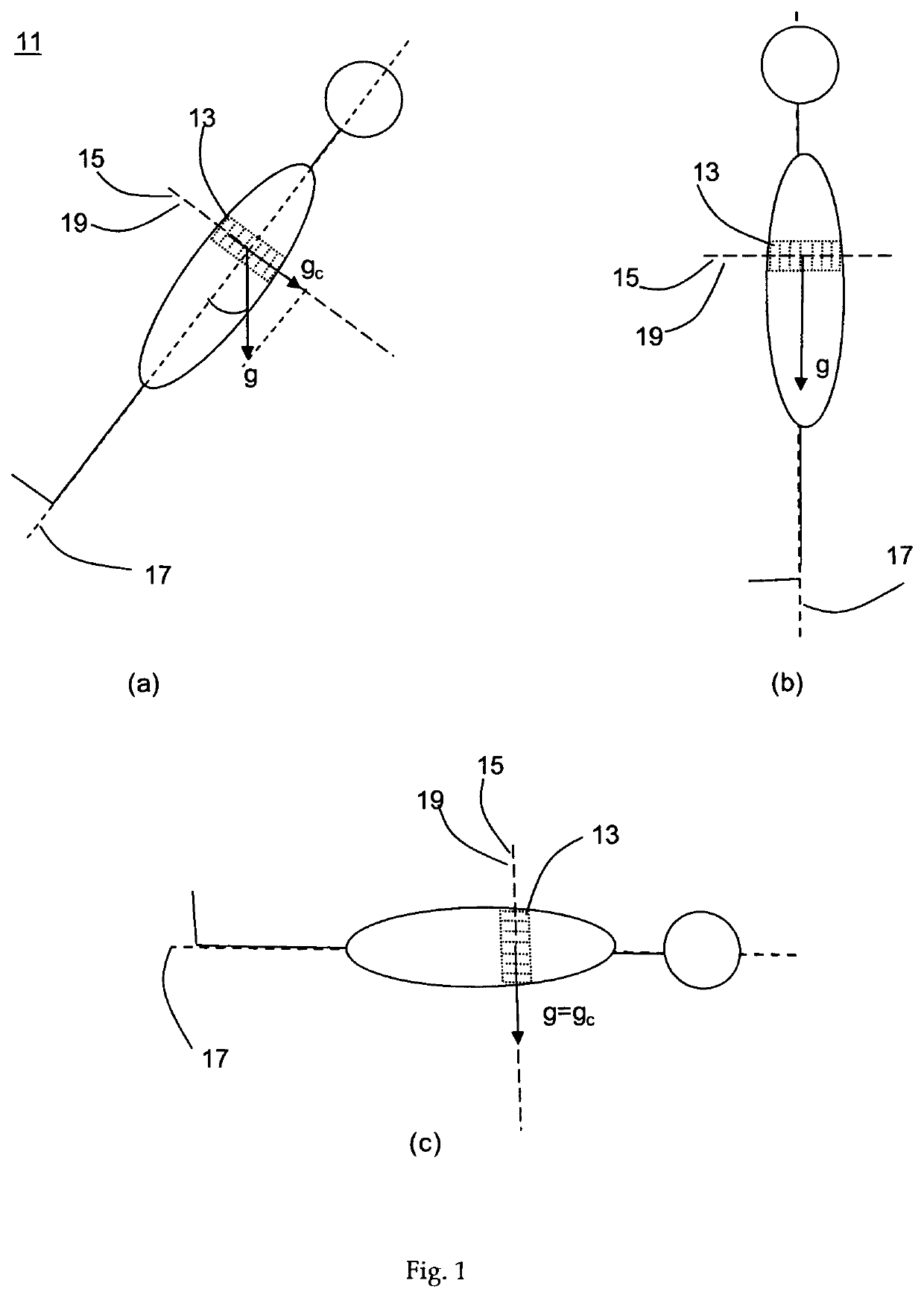
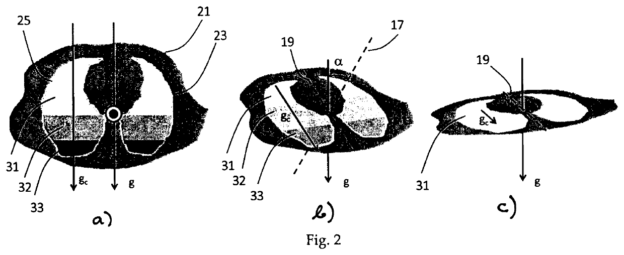
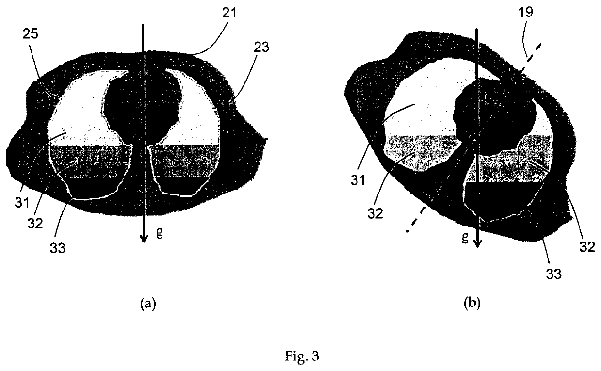
[0026]The inventive sensor device for EIT imaging, comprising an electrode array for measuring an impedance distribution, is characterized in that at least one sensor for gathering spatial information (i.e. for determining spatial orientation of a test person) is coupled to the electrode array. The spatial information comprises information about the orientation and / or position of the sensor. The sensor may for example be affixed at the electrode array itself or may be positioned in a defined relation with respect to the electrode array and therefore with respect to a body part which is tested. Consequently, the spatial information comprises information about the orientation and / or position of a test subject (test person), notably the body part tested. Advantageously in practice said spatial information describes the spatial orientation and / or position of the electrode array, which is affixed to a test subject. Data of the position and / or orientation of the sensor can be transformed into data defining the orientation of the body part tested with respect to the gravitational vector, i.e. with respect to the direction of the gravity vector. Thus, e.g. when impedance of the thorax (or another body part) is measured, the spatial information gathered describes the orientation of the thorax, and thus of the lungs (or said other body part), with regard to the gravitational force. Spatial information about orientation and position of a test person, in particular of an electrical impedance tested body part, is prerequisite for adjusting impedance distribution measurement data with regard to gravitational influences. At least one sensor for determining spatial orientation of a test subject may be coupled to the electrode array. Hereby, for example, the spatial orientation of the test subject is determined in relation to the direction of the gravity vector.
[0027]The additional spatial information described is highly useful to create clinically usable images and movies. A device that is able to provide reliable EIT difference images depending on body position has not been described previously.
[0028]Advantageously the at least one sensor for determining spatial orientation of a test person comprises a spatial data sensor, such as a three-dimensional acceleration sensor, which is also called tri-axial acceleration sensor or gravity sensor. This sensor is used to determine the position or orientation, advantageously, with respect to the gravity vector. A simple acceleration sensor, such as e.g. a mono-axial acceleration sensor, which is able to detect movements only, but which is not able to measure position or orientation, does not suffice for the mentioned purpose.

Problems solved by technology

However, lung recruitment manoeuvres entail risks.
Unfortunately, this is often too late.

Method used


Image

  • Sensor device for electrical impedance tomography imaging, electrical impedance tomography imaging instrument and electrical impedance tomography method
  • Sensor device for electrical impedance tomography imaging, electrical impedance tomography imaging instrument and electrical impedance tomography method
  • Sensor device for electrical impedance tomography imaging, electrical impedance tomography imaging instrument and electrical impedance tomography method

Examples


example

[0087]Below is depicted an example for reconstructing an EIT image by using the finite element method and adjusting raw EIT data with respect to position and orientation of the patient according to present invention.

[0088]The reconstruction problem is solved using the finite-element method (FEM). The FEM uses a mesh of triangular elements, defined by nodes, to discretize the space or surface of interest. Then the physics of the problem is applied to the mesh and the problem is solved using given boundary conditions.

[0089]Doing this for EIT, one gets

Y(σ)*V=C,

[0090]where Y is the conductance matrix, depending on the conductivity σ, V is a set of voltage distribution and C is a set of applied currents.

[0091]Given that one can only measure the voltage at the medium's boundary at given locations (i.e. at the electrodes) the operator D is introduced. It returns a vector v of voltage measurements corresponding to a given system and scanning pattern,

v=D(V)=D(Y−1*C).

[0092]The above equation...


PUM


Abstract

A sensor device for EIT imaging comprises an electrode array for measuring an impedance distribution, with at least one sensor for determining spatial orientation of the electrode array coupled to the electrode array. An EIT imaging instrument is connectable to a sensor for determining spatial orientation of a test person, and optionally in addition connectable to a sensor for gathering information on electrical and / or acoustic activity and / or a sensor for gathering information on dilation. A computing device is connected or integrated for adjusting impedance data based on spatial data, which spatial data describe the spatial orientation of a test subject. An EIT imaging method for measuring an impedance distribution and adjusting said measured impedance distribution comprises measuring impedance distribution by using an impedance distribution measuring device comprising an electrode array, and transforming the measured impedance distribution into EIT images.

Description

CROSS-REFERENCE TO RELATED APPLICATIONS[0001]This application is a national phase entry under 35 U.S.C. § 371 of PCT / CH2011 / 000236 filed Oct. 4, 2011, which claims priority to Swiss Patent Application No. 1638 / 10 filed Oct. 7, 2010, the entirety of each of which is incorporated by this reference.TECHNICAL FIELD OF THE INVENTION[0002]This invention relates to a sensor device for electrical impedance tomography imaging (EIT imaging) comprising an electrode array for measuring an impedance distribution, an EIT imaging instrument connectable to a sensor device comprising an electrode array, an EIT imaging method for measuring an impedance distribution and adjusting said measured impedance distribution.BACKGROUND OF THE INVENTION[0003]Electrical impedance tomography (EIT) is a non-invasive imaging technique used to investigate and measure regional lung ventilation and perfusion (flow of blood) in humans and animals. In contrast to conventional methods, EIT does not require the patient to...

Claims


Application Information

Patent Timeline
Patent Type & Authority Patents(United States)
IPC IPC(8): A61B5/0205A61B5/113A61B5/0408A61B5/00A61B7/00
CPCA61B7/003A61B5/04085A61B5/0205A61B5/1135A61B5/6831A61B5/0536A61B5/061A61B5/08A61B5/6802A61B5/282
Inventor BRUNNER, JOSEF X.GAGGERO, PASCAL OLIVIERROBITAILLE, NICOLAS
Owner SWISSTOM
Learn More