
Jaw crusher retraction assembly

a technology of retraction assembly and jaw crusher, which is applied in the direction of grain treatment, etc., can solve the problems of accelerated wear of the pivot mounting of the retraction rod and the cylinder, disadvantages of conventional retraction assembly, etc., to facilitate the mounting of the jaw crusher, reduce stress and load, and prolong the operational life of the crusher component parts

Active Publication Date: 2020-02-04
SANDVIK INTELLECTUAL PROPERTY AB
View PDF18 Cites 0 Cited by
  • Summary
  • Abstract
  • Description
  • Claims
  • Application Information

AI Technical Summary

Benefits of technology

[0007]It is an objective of the present invention to provide a retraction assembly or system for a jaw crusher that is mechanically robust and configured to minimise stress and loading forces on various components of the assembly so as to extend the operational lifetime of the crusher component parts. It is a further specific objective to provide a compact movable jaw mounting assembly to facilitate mounting of a jaw crusher within confined or otherwise obstructed locations. It is a yet further objective to provide a retraction assembly that is compatible for use with both wedge and shim settings and to avoid the requirement to modify the retraction assembly significantly between wedge and shim setting changes.
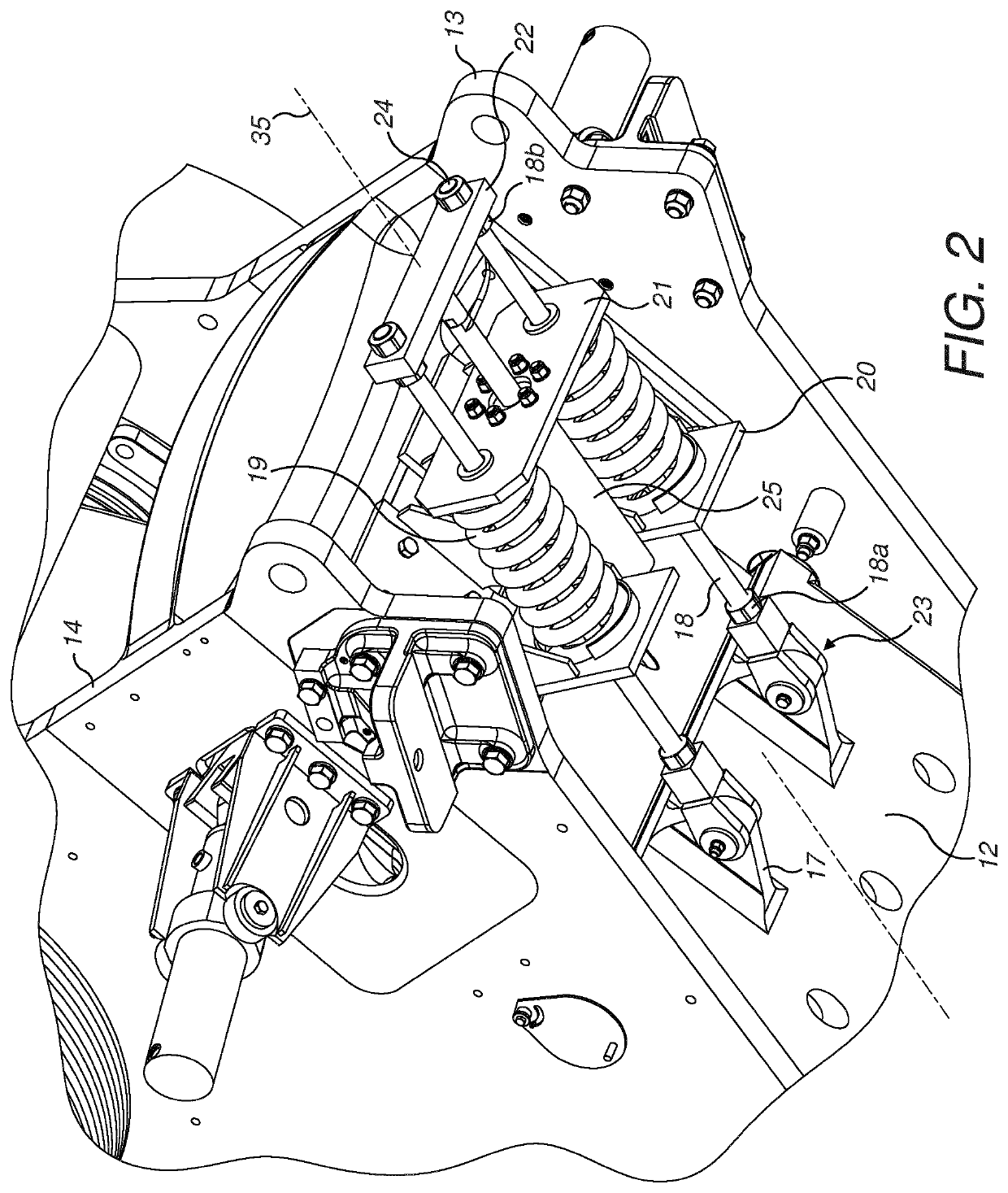
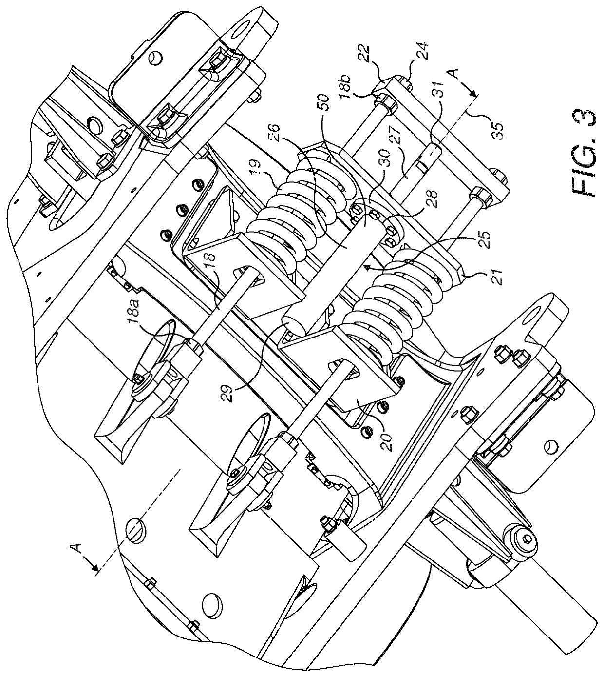
[0008]The objectives are achieved by a retraction assembly that minimise torque resultant from the relative positioning of the retraction assembly component parts and in particular the spatial separation distance between selected components of the assembly relative to the pivoted mounting position of the assembly at the lower end of the movable jaw. In particular, according to the subject invention, a cylinder that forms part of the assembly, is positioned specifically in the axial direction as close as possible to the lower region of the movable jaw. Accordingly, the contribution to the torque resultant from the mass of the cylinder is reduced which in turn reduces the stress and wear of the various components of the assembly including the cylinder, the pivot mounts and other mounting regions and components. Additionally, due to the relative positioning of the cylinder via a first and second mounting boss, the total axial length of the retraction assembly is minimised without compromising the function and performance of the assembly to control and stabilise the toggle unit, the oscillating movement of the movable jaw and potentially the control of the close side setting (CSS). In particular, the present retraction assembly comprises a compact design and is generally shorter in total length relative to conventional arrangements. Accordingly, the present assembly is capable of being contained within the overall footprint the jaw crusher and does not protrude at least excessively at the lower and rear region of the jaw crusher which is otherwise a feature of conventional retraction assemblies.
[0009]The present invention is advantageous to maximise the service lifetime of the component parts of the assembly via the relative positioning of selected components and does not require exclusive or sophisticated component parts to achieve a robust and compact constructions.

Problems solved by technology

However, conventional retraction assemblies are disadvantageous for a number of reasons.
In particular, the pivot mountings of the retraction rods and the cylinder are subject to accelerated wear due to the continued transmission of loading forces and torque.
Additionally, the combined axial length of existing linkage assemblies is often difficult to accommodate within the limited space available at the lower, rear region of the crusher which creates problems when it is required to mount the crusher within confined spaces.

Method used


Image

  • Jaw crusher retraction assembly
  • Jaw crusher retraction assembly
  • Jaw crusher retraction assembly

Examples


Embodiment Construction

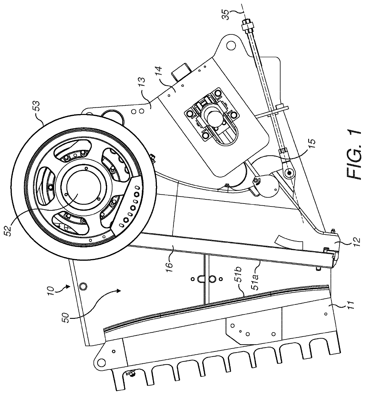
[0029]Referring to FIG. 1, a jaw crusher 10 comprises a first stationary jaw 11 and a second movable jaw 12. Each jaw mounts a respective jaw plate 51a, 51b in opposed relationship to define a crushing zone 50 extending lengthwise between the stationary and movable jaws 11, 12. Movable jaw 12 is mounted and suspended towards its upper end via a shaft (not shown) having axial ends covered by respective end caps 52. A pair of flywheels 53 communicate rotational drive to the shaft to impart an oscillating gyroscopic motion to movable jaw 12 to increase and decrease the volume of the crushing zone 50 and accordingly crush material introduced into the zone 50 between the plates 51a, 51b.

[0030]The oscillating motion of movable jaw 12 is stabilised by a mechanically actuated link assembly provided at a lower, rear region of the jaw crusher 10. The actuated link assembly comprises a toggle unit 15 coupled between a lower part of movable jaw 12 and a back-frame-end 14. Back-frame-end 14 is ...


PUM


Abstract

A jaw crusher retraction assembly having a base, a first and second mount boss, a resiliently biased component and an actuating cylinder. The cylinder and resiliently biased component are mounted axially between respective regions of the base and the first and second bosses so as to minimize stress in the retraction assembly components and to provide a compact overall design.

Description

RELATED APPLICATION DATA[0001]This application is a § 371 National Stage Application of PCT International Application No. PCT / EP2016 / 082228 filed Dec. 21, 2016.FIELD OF INVENTION[0002]The present invention relates to a jaw crusher retraction assembly to form part of a mechanically actuated link assembly for the supported oscillating movement of a movable jaw of a jaw crusher and in particular, although not exclusively, to a retraction assembly to provide controlled axial compression of parts of the link assembly.BACKGROUND ART[0003]Jaw crushers typically comprise a fixed jaw and a movable jaw that together define a crushing zone. A drive mechanism is operative to rock the movable jaw back and forth in order to crush material within this zone. The crushing zone is generally convergent towards its lower discharge end so that crushable material, fed to an upper and wider end of the zone, is capable of falling downward under gravity whilst being subject to repeated cycles of crushing mo...

Claims


Application Information

Patent Timeline
Patent Type & Authority Patents(United States)
IPC IPC(8): B02C1/02B02C1/04
CPCB02C1/04B02C1/025B02C1/10
Inventor SJOBECK, ROGERLINDBERG, MARTEN
Owner SANDVIK INTELLECTUAL PROPERTY AB
Learn More