Detector with reduced fluorescence range noise

a technology of fluorescence range noise and detector, which is applied in the direction of fluorescence/phosphorescence, instruments, condensers, etc., can solve the problems of large benchtop footprint and relatively high cost of optical systems, and achieve the effect of reducing fluorescence range nois

Active Publication Date: 2020-02-04
ILLUMINA INC
View PDF21 Cites 6 Cited by
  • Summary
  • Abstract
  • Description
  • Claims
  • Application Information

AI Technical Summary

Benefits of technology

[0006]There is set forth herein a device comprising: structure defining a detector surface configured for supporting biological or chemical substances, and a sensor array comprising light sensors and circuitry to transmit data signals using photons detected by the light sensors. The device can include one or more feature for reducing fluorescence range noise in a detection band of the sensor array.

Problems solved by technology

However, such optical systems can be relatively expensive and require a larger benchtop footprint.

Method used


Image

  • Detector with reduced fluorescence range noise
  • Detector with reduced fluorescence range noise
  • Detector with reduced fluorescence range noise

Examples


Embodiment Construction

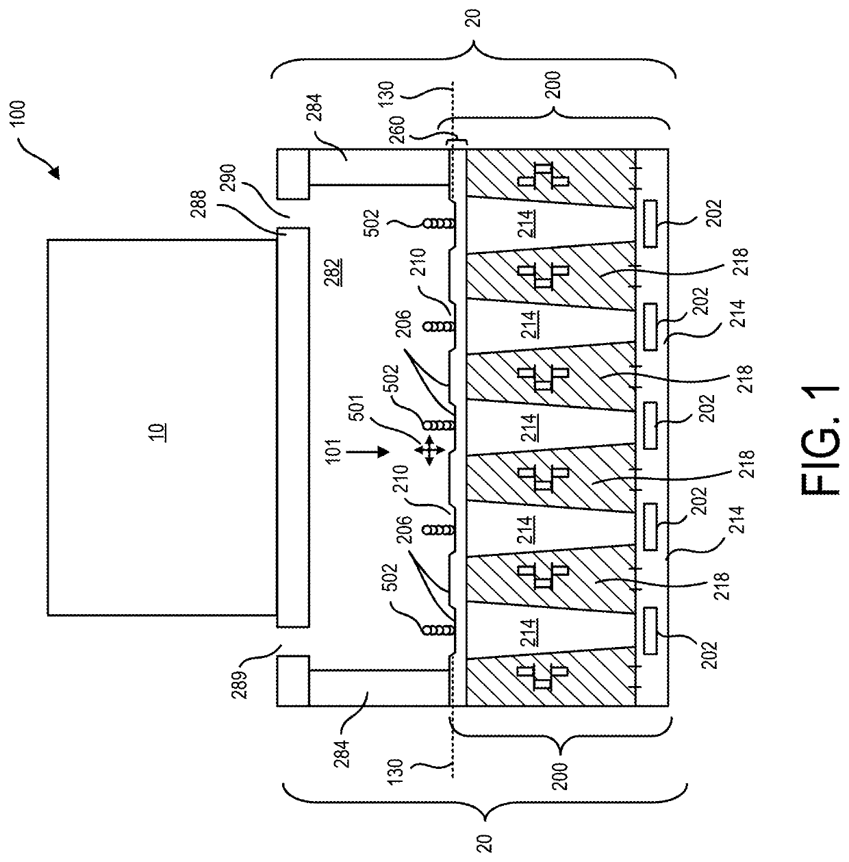
[0021]In FIG. 1 there is shown a system 100 for use in analysis, such as biological or chemical analysis. System 100 can include light energy exciter 10 and a detector assembly 20. Detector assembly 20 can include detector 200 and a flow cell 282. Detector 200 can include a plurality of light sensors 202 and detector surface 206 for supporting samples 502 such as biological or chemical samples subject to test. Detector 200 can also include a plurality of light guides that guide light from detector surface 206 to light sensors 202. Detector surface 206, sidewalls 284, and flow cover 288 can define and delimit flow cell 282. Detector surface 206 can have an associated detector surface plane 130.

[0022]In a further aspect, detector surface 206 can be recessed to include reaction recesses 210 (nanowells). According to one example, each light sensor 202 can be aligned to one light guide 214 and one reaction recess 210. Each reaction recess 210 can define therein one or more reaction sites...


PUM

PropertyMeasurementUnit
center (peak) wavelengthaaaaaaaaaa
) wavelengthaaaaaaaaaa
center wavelengthaaaaaaaaaa

Abstract

There is set forth herein a device comprising structure defining a detector surface configured for supporting biological or chemical substances, and a sensor array comprising light sensors and circuitry to transmit data signals using photons detected by the light sensors. The device can include one or more features for reducing fluorescence range noise in a detection band of the sensor array.

Description

CROSS-REFERENCE TO RELATED APPLICATION[0001]This application claims priority to U.S. Patent Application No. 62 / 611,464, filed Dec. 28, 2017, entitled, “Detector With Reduced Fluorescence Range Noise,” which is incorporated herein by reference in its entirety. This application also claims priority to U.S. Patent Application No. 62 / 644,804, filed Mar. 19, 2018, entitled, “Detector With Reduced Fluorescence Range Noise,” which is incorporated herein by reference in its entirety.BACKGROUND[0002]Various protocols in biological or chemical research involve performing controlled reactions. The designated reactions can then be observed or detected and subsequent analysis can help identify or reveal properties of chemicals involved in the reaction.[0003]In some multiplex assays, an unknown analyte having an identifiable label (e.g. fluorescent label) can be exposed to thousands of known probes under controlled conditions. Each known probe can be deposited into a corresponding well of a micro...

Claims


Application Information

Patent Timeline
Patent Type & Authority Patents(United States)
IPC IPC(8): G01N21/64G01N33/53
CPCG01N21/6454G01N33/53G01N21/6428G01N2201/08G01N2021/6471G01N21/6486G01N21/6402G01N21/01G02B5/223H01L27/14643H01L27/14621H01L27/14625G02B19/0076G02B19/0019G01N2021/6463
Inventor FUNG, TRACY H.SABOUNCHI, POORYAHIRSCHBEIN, BERNARDPINTO, JOSEPHKHURANA, TARUNSMITH, RANDALLFENG, WENYI
Owner ILLUMINA INC
Why Eureka
Try Eureka