Robot, robot control apparatus and robot system

a robot control and robot technology, applied in the field of robots, can solve the problems of false detection of second markers, difficult to correctly teach the position of reference points, and difficulty in correctly operating the arm, so as to set the offset more accurately, and reduce human errors and variations

Active Publication Date: 2020-02-04
SEIKO EPSON CORP
View PDF12 Cites 1 Cited by
  • Summary
  • Abstract
  • Description
  • Claims
  • Application Information

AI Technical Summary

Benefits of technology

[0011]According to this configuration, in the robot, the movable part performs the action based on the position of the first marker obtained using the first position and attitude of the movable part when the first image containing the first marker is captured by the imaging unit provided in the movable part and the second position and attitude of the movable part when the second image containing the first marker is captured by the imaging unit. Thereby, the robot may accurately perform a job including the action based on the position of the first marker without operation of the movable part by an operator.
[0086]In the robot system, the control apparatus sets the offset of the predetermined part with respect to the arm in the robot based on the images captured by the imaging unit in the first state and the third state. Thereby, in the robot system, the control apparatus may set the offset more accurately and easily than in the case where the operator operates the arm to set the offset of the tool in the robot while teaching the position of the reference point.

Problems solved by technology

However, it is not easy to correctly operate the arm while visually specifying the states in which the tool is barely in contact with the reference point.
That is, in the technology described in Patent Document 1, it may be difficult to correctly teach the position of the reference point.
According to the technology described in Patent Document 2, the pattern for calibration may cause false detection of the second marker.
As a result, it may be impossible for an apparatus that detects a position indicated by a geometric position relationship between the first markers and the second marker to accurately detect the position.
However, it is not easy to correctly operate the arm while visually specifying the states in which the tool is barely in contact with the reference point.
That is, in the technology described in Patent Document 3, it may be difficult to correctly teach the position of the reference point.
Further, if the offset of the tool is set while the position of the reference point is correctly taught, the time taken for the setting may be longer.

Method used


Image

  • Robot, robot control apparatus and robot system
  • Robot, robot control apparatus and robot system
  • Robot, robot control apparatus and robot system

Examples


first embodiment

[0140]As below, an embodiment of the invention will be explained with reference to the drawings.

Configuration of Robot System

[0141]First, a configuration of a robot system 1 will be explained.

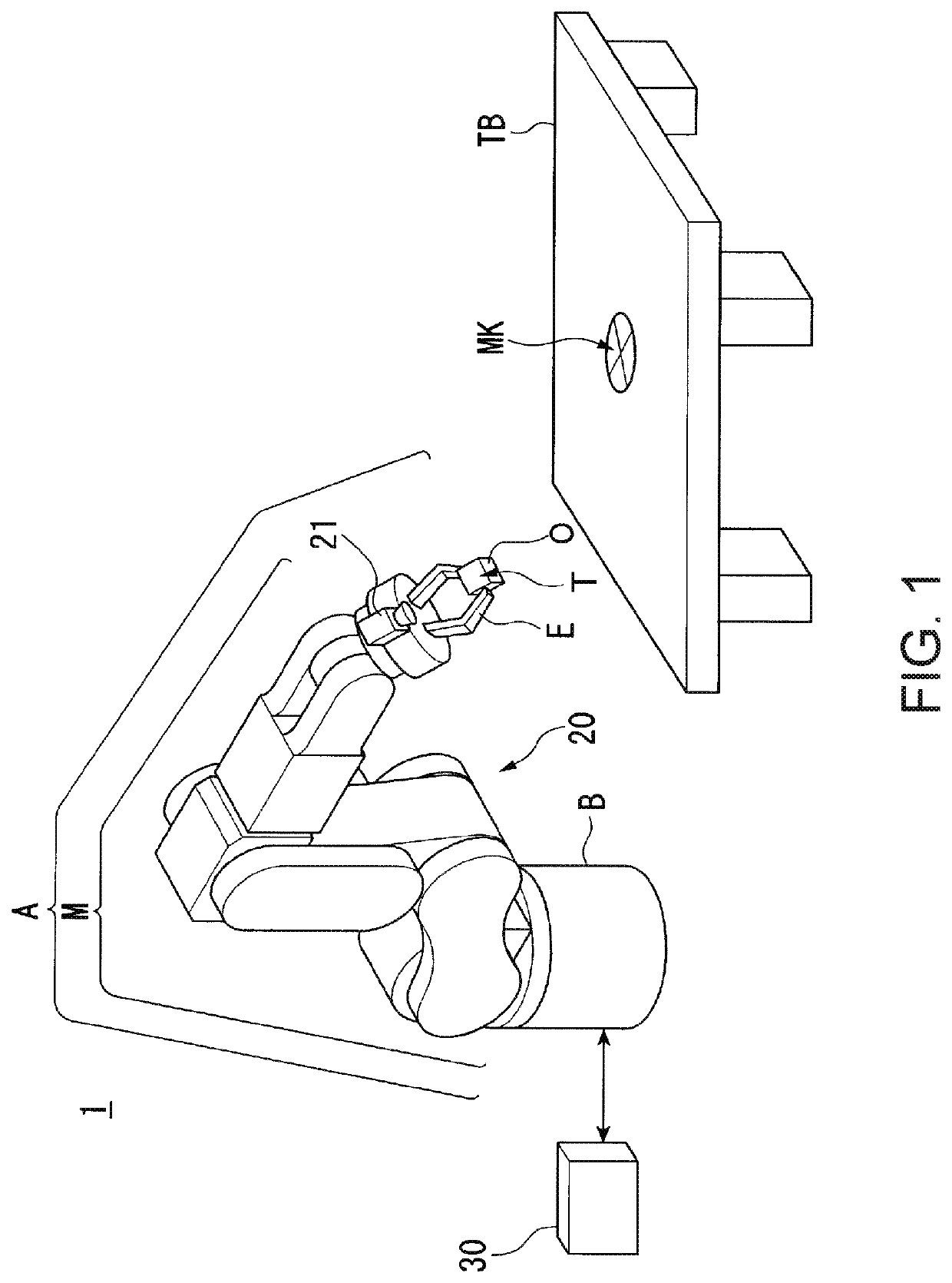
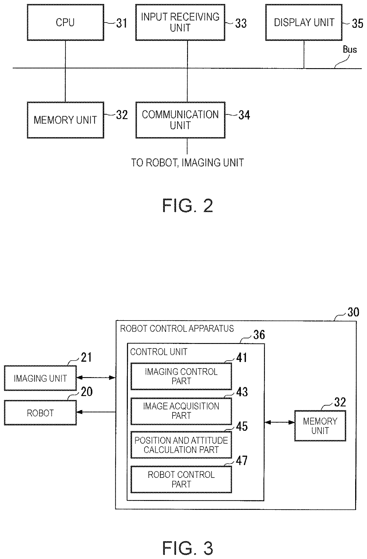
[0142]FIG. 1 shows an example of the configuration of the robot system 1 according to the embodiment. The robot system 1 includes a robot 20 and a robot control apparatus 30.

[0143]The robot 20 is a single-arm robot including an arm A and a support B that supports the arm A. The single-arm robot is a robot having a single arm like the arm A in the example. Note that the robot 20 may be a multi-arm robot in place of the single-arm robot. The multi-arm robot is a robot having two or more arms (e.g. two or more arms A). Of the multi-arm robots, a robot having two arms is also called a dual-arm robot. That is, the robot 20 may be a dual-arm robot having two arms or a multi-arm robot having three or more arms (e.g. three or more arms A). Alternatively, the robot 20 may be another robot such as a scal...

modified example 1 of embodiment

[0231]As below, referring to FIG. 15, Modified Example 1 of the embodiment will be explained.

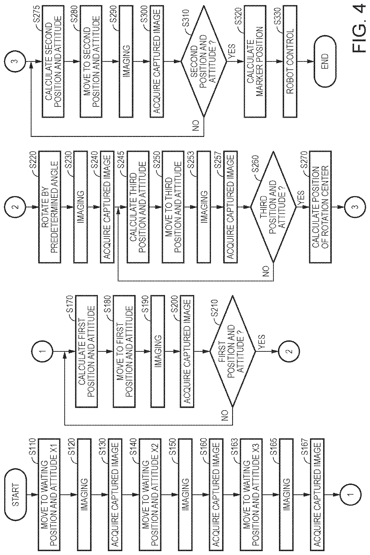
[0232]The robot control apparatus 30 may be adapted, after calculating the position of the first marker MK at step S320 shown in FIG. 4, to store relative position information representing the relative position between the current position of the control point T (i.e., the position of the control point T when the position and the attitude of the control point T coincide with the second position and attitude) and the position of the first marker MK in the memory unit 32. In this case, the robot control apparatus 30 may detect (calculate) another marker provided in a different position from that of the first marker MK and second marker MK2 as a marker provided on the top surface of the worktable TB based on the relative position information.

[0233]Specifically, as shown in FIG. 15, the robot control apparatus 30 moves the position of the control point T with the attitude of the control point T ...

modified example 2 of embodiment

[0237]As below, Modified Example 2 of the embodiment will be explained. The robot control apparatus 30 may be adapted so that information representing relative position and attitude between the position and the attitude of the control point T and a position and an attitude of a coincidence point in the range that can be imaged by the imaging unit 21 may be stored in the memory unit 32 in advance. In this case, the robot control apparatus 30 allows the position and the attitude of the control point T to coincide with the first position and attitude in the processing at step S180 shown in FIG. 4, and then, calculates the position of the first marker MK based on the first position and attitude and the information stored in the memory unit 32 in advance. Thereby, the robot control apparatus 30 may shorten the time taken for the detection of the position of the first marker MK.

[0238]As described above, in the robot 20, a movable part (in the example, the arm A) performs actions based on ...


PUM


Abstract

A robot includes a movable part, and the movable part performs an action based on a position of a first marker obtained using first position and attitude of the movable part when a first image containing the first marker is captured by an imaging unit provided in the movable part and second position and attitude of the movable part when a second image containing the first marker is captured by the imaging unit.

Description

BACKGROUND1. Technical Field[0001]The present invention relates to a robot, a robot control apparatus, and a robot system.2. Related Art[0002]Research and development of methods for teaching actions of robots to robot control apparatuses that operate the robots are carried out.[0003]A direct teaching apparatus that allows a robot to be manually operated and a robot control apparatus to store positions and attitudes thereof is known (see Patent Document 1 (JP-A-08-216074)).[0004]Further, research and development of technologies for imaging objects using imaging units and allowing robots to perform predetermined jobs based on the captured images are carried out. In the technologies, a calibration of correlating coordinates in a robot coordinate system as a coordinate system of a robot and coordinates in an imaging unit coordinate system as a coordinate system of an imaging unit may be performed. In the calibration, for example, a pattern for calibration is imaged by the imaging unit a...

Claims


Application Information

Patent Timeline
Patent Type & Authority Patents(United States)
IPC IPC(8): G05B19/00B25J13/02B25J9/16B25J9/10G05B19/408B25J13/00G16Z99/00
CPCB25J9/16B25J13/02B25J9/10G05B19/4086G16Z99/00G05B2219/40B25J13/00B25J9/1697B25J19/021G05B2219/39022
Inventor YAMAGUCHI, YUKIHIROISHIGE, TAROHARADA, ATSUSHI
Owner SEIKO EPSON CORP
Why Eureka
Try Eureka